Greensmaster 3320/3420
Hydraulic System
Page 5 -- 58
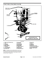
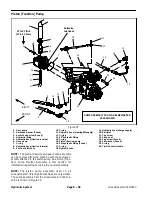
Piston Pump Installation (Fig. 39)
1. Make sure the flange surfaces of the gear pump and
piston pump are thoroughly clean.
2. Install gear pump to the piston pump (see Gear
Pump Installation in this section).
3. If removed, secure pump coupling to piston pump
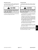
shaft (Fig. 40 or 41):
A. Make sure that pump shaft and bore of coupling
are thoroughly cleaned.
B. Position key to pump shaft.
C. Apply Loctite #242 (or equivalent) to the threads
of the cap screw used to secure coupling to pump
shaft.
D. Slide coupling onto pump shaft and secure with
spacer and cap screw. Torque cap screw from
27 to
33 ft--lb (37 to 44 N--m)
.
4. Inspect threads and sealing surfaces of hydraulic fit-
tings and hydraulic hose connectors. Replace any dam-
aged or worn fittings or connectors.
5. Lubricate and place new O--rings onto all removed
hydraulic fittings. Install fittings into pump openings
making sure that fitting orientation is as noted during re-
moval. Tighten fittings (see Hydraulic Fitting Installation
in the General Information section of this chapter).
6. Insert coupling on pump shaft into coupling attached
to engine and slide pump assembly to pump mount. Se-
cure pump assembly to pump mount with two (2) cap
screws (item 23) and flat washers (item 24).
7. Remove plugs that were placed during disassembly
from hydraulic fittings and hoses.
8. Using labels placed during pump removal, lubricate
new O--rings and connect hydraulic hoses to gear pump
and piston pump fittings. Tighten hose connections (see
Hydraulic Hose and Tube Installation in the General In-
formation section of this chapter).
9. Connect the traction control cable to the neutral arm:
A. Secure cable ball joint to neutral arm with cap
screw (item 21) and flange nut (item 22).
B. Secure control cable to neutral arm with cable
jam nuts. Make sure that a lock washer is positioned
on each side of the neutral arm.
10.Remove clamp from gear pump suction hose (item
9).
11. Check oil level in hydraulic reservoir and add correct
oil if necessary.
12.Follow Hydraulic System Start--up procedures (see
Hydraulic System Start--up in this section).
13.Check neutral position of the traction pedal. If adjust-
ment is required, see Adjust Transmission for Neutral in
the Traction Unit Owners Manual.
Summary of Contents for Greensmaster 3420 TriFlex
Page 2: ...Greensmaster 3320 3420 This page is intentionally blank ...
Page 4: ...Greensmaster 3320 3420 This page is intentionally blank ...
Page 6: ...Greensmaster 3320 3420 This page is intentionally blank ...
Page 24: ...Greensmaster 3320 Page 3 6 Gasoline Engine This page is intentionally blank ...
Page 38: ...Greensmaster 3420 Page 4 4 Diesel Engine This page is intentionally blank ...
Page 54: ...Greensmaster 3420 Page 4 20 Diesel Engine This page is intentionally blank ...
Page 56: ...Greensmaster 3320 3420 Hydraulic System Page 5 2 This page is intentionally blank ...
Page 150: ...Greensmaster 3320 3420 Hydraulic System Page 5 96 This page is intentionally blank ...
Page 250: ...Greensmaster 3320 3420 Page 6 100 Electrical System This page is intentionally blank ...
Page 277: ...Greensmaster 3320 3420 Page 7 27 Chassis This page is intentionally blank Chassis ...
Page 325: ...Greensmaster 3320 3420 Groomer Page 9 13 This page is intentionally blank Groomer ...
Page 340: ...Greensmaster 3320 3420 Page 10 2 Foldout Drawings This page is intentionally blank ...
Page 347: ...Page 10 9 This page is intentionally blank ...
Page 356: ...Page 10 18 E Reels Wire Harness Drawing Greensmaster 3320 3420 Serial Number Below 312000000 ...
Page 358: ...Page 10 20 E Reels Wire Harness Drawing Greensmaster 3320 3420 Serial Number Above 312000000 ...
Page 360: ...Page 10 22 This page is intentionally blank ...


