Greensmaster 3320/3420
Groomer
Page 9 -- 9
Installation
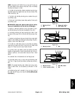
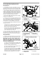
1. If removed, install shaft into groomer cover (Fig. 6):
A. Install new O--ring into groove of shaft.
B. Apply antiseize lubricant to shaft surface that is
below the retaining ring groove.
C. Slide shaft up through bore of cover and secure
with thrust washer and retaining ring. Position shaft
in cover so that cam point of shaft is located away
from the gasket surface (Fig. 7).
D. Install plunger detent into groomer cover so that
end of plunger if from
flush to 0.020” (0.5 mm)
ex-
tending from cover surface (Fig. 7).
E. Slide handle into shaft so that it extends toward
the front of the cover.
F. Apply Loctite #242 (or equivalent) to threads of
set screw. Install set screw into end of shaft to secure
handle in place.
2. Install groomer cover assembly to RH drive plate as-
sembly (Fig. 5):
A. Make sure that handle on groomer cover is ro-
tated toward the front of the machine.
B. Fill groomer cover with approximately five (5)
ounces (142 grams) of Mobil XHP221 grease (or
equivalent).
C. Install new gasket and then groomer cover as-
sembly to RH drive plate. Secure cover with five (5)
flange head screws.
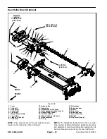
3. If equipped, install rear roller brush to cutting unit
(see Rear Roller Brush Installation in the Service and
Repairs section of Chapter 8 -- DPA Cutting Units).
4. After belt installation is complete, connect the cutting
unit power disconnect couplers.
1. Shaft
2. Cam point
3. Plunger detent
Figure 7
2
1
3
Flush to 0.020”
(Flush to 0.5 mm)
Groomer
Summary of Contents for Greensmaster 3420 TriFlex
Page 2: ...Greensmaster 3320 3420 This page is intentionally blank ...
Page 4: ...Greensmaster 3320 3420 This page is intentionally blank ...
Page 6: ...Greensmaster 3320 3420 This page is intentionally blank ...
Page 24: ...Greensmaster 3320 Page 3 6 Gasoline Engine This page is intentionally blank ...
Page 38: ...Greensmaster 3420 Page 4 4 Diesel Engine This page is intentionally blank ...
Page 54: ...Greensmaster 3420 Page 4 20 Diesel Engine This page is intentionally blank ...
Page 56: ...Greensmaster 3320 3420 Hydraulic System Page 5 2 This page is intentionally blank ...
Page 150: ...Greensmaster 3320 3420 Hydraulic System Page 5 96 This page is intentionally blank ...
Page 250: ...Greensmaster 3320 3420 Page 6 100 Electrical System This page is intentionally blank ...
Page 277: ...Greensmaster 3320 3420 Page 7 27 Chassis This page is intentionally blank Chassis ...
Page 325: ...Greensmaster 3320 3420 Groomer Page 9 13 This page is intentionally blank Groomer ...
Page 340: ...Greensmaster 3320 3420 Page 10 2 Foldout Drawings This page is intentionally blank ...
Page 347: ...Page 10 9 This page is intentionally blank ...
Page 356: ...Page 10 18 E Reels Wire Harness Drawing Greensmaster 3320 3420 Serial Number Below 312000000 ...
Page 358: ...Page 10 20 E Reels Wire Harness Drawing Greensmaster 3320 3420 Serial Number Above 312000000 ...
Page 360: ...Page 10 22 This page is intentionally blank ...


