Greensmaster 3320/3420
DPA Cutting Units
Page 8 -- 3
General Information
Cutting Unit Operator’s Manual
The Cutting Unit Operator’s Manual provides informa-
tion regarding the operation, general maintenance and
maintenance intervals for the DPA cutting units on your
Greensmaster TriFlex Hybrid machine. Additionally, if
optional kits have been installed on the cutting units (e.g.
rear roller brush), the installation instructions for the kit
includes set--up and operation information. Refer to
those publications for additional information when ser-
vicing the cutting units.
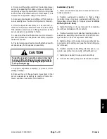
Supporting Cutting Unit when Servicing
Whenever the cutting unit has to be tipped to expose the
bedknife or cutting reel, support the rear of the cutting
unit to make sure the lock nuts on the back of the bedbar
adjusting screws are not resting on the work surface.
1. Lock nut
2. Support
Figure 2
1
1
2
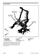
Opening Electrical Circuit to Cutting Units
CAUTION
Before installing, removing or servicing the cut-
ting units, separate the cutting unit power dis-
connect. This will prevent unexpected cutting
unit operation.
Before installing, removing or working on the cutting
units, disconnect the cutting units from the electrical
power supply by separating the cutting unit power dis-
connect couplers (Fig. 3). The couplers are located at
the base of the rollover bar on the left side of the traction
unit. Connect the couplers together before operating the
machine.
1. Coupler
2. Stationary coupler
Figure 3
1
2
DP
A
Cutt
in
g
Un
its
Summary of Contents for Greensmaster 3420 TriFlex
Page 2: ...Greensmaster 3320 3420 This page is intentionally blank ...
Page 4: ...Greensmaster 3320 3420 This page is intentionally blank ...
Page 6: ...Greensmaster 3320 3420 This page is intentionally blank ...
Page 24: ...Greensmaster 3320 Page 3 6 Gasoline Engine This page is intentionally blank ...
Page 38: ...Greensmaster 3420 Page 4 4 Diesel Engine This page is intentionally blank ...
Page 54: ...Greensmaster 3420 Page 4 20 Diesel Engine This page is intentionally blank ...
Page 56: ...Greensmaster 3320 3420 Hydraulic System Page 5 2 This page is intentionally blank ...
Page 150: ...Greensmaster 3320 3420 Hydraulic System Page 5 96 This page is intentionally blank ...
Page 250: ...Greensmaster 3320 3420 Page 6 100 Electrical System This page is intentionally blank ...
Page 277: ...Greensmaster 3320 3420 Page 7 27 Chassis This page is intentionally blank Chassis ...
Page 325: ...Greensmaster 3320 3420 Groomer Page 9 13 This page is intentionally blank Groomer ...
Page 340: ...Greensmaster 3320 3420 Page 10 2 Foldout Drawings This page is intentionally blank ...
Page 347: ...Page 10 9 This page is intentionally blank ...
Page 356: ...Page 10 18 E Reels Wire Harness Drawing Greensmaster 3320 3420 Serial Number Below 312000000 ...
Page 358: ...Page 10 20 E Reels Wire Harness Drawing Greensmaster 3320 3420 Serial Number Above 312000000 ...
Page 360: ...Page 10 22 This page is intentionally blank ...


