Greensmaster 3320/3420
DPA Cutting Units
Page 8 -- 34
IMPORTANT: The brush drive belt may fail prema-
turely if the pulleys are not properly aligned.
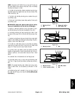
4. Check alignment of pulleys with a straight edge
placed along the outer face of the pulleys (Fig. 40). The
outer faces of the drive, driven and idler pulleys should
be aligned. If necessary to align pulleys, loosen locking
collars on brush bearings and move brush assembly un-
til pulleys are aligned. Once pulleys are aligned, secure
brush with bearing locking collars.
IMPORTANT: Make sure that idler pulley is loos-
ened before installing brush drive belt.
5. To install brush drive belt (item 2):
A. Make sure that idler pulley (item 6) is loose on
drive plate.
B. Carefully install drive belt around drive, driven
and idler pulleys.
C. After belt installation, make sure that belt and
pulley grooves are aligned and that belt is centered in
pulleys.
6. To tension the drive belt:
A. Push down on the idler pulley and secure with cap
screw (item 22) and flange nut (item 8). Make sure
that cover plate (item 7) is covering the slot in the
drive plate to prevent debris from entering the brush
drive area.
B. After idler pulley is secured, check that drive belt
has approximately 1/4” (6 mm) deflection at the cen-
ter of the belt with 2 lb (1 kg) of force applied to the
belt (Fig. 41).
7. Check that roller brush is parallel to rear roller with
0.010” (0.25 mm) clearance to light contact with roller.
If contact is incorrect, brush operation will be adversely
affected.
8. Lubricate grease fittings on brush support and drive
plate until grease is visible. Wipe up excess grease.
1. Drive pulley
2. Driven pulley
3. Idler pulley
4. Drive belt
Figure 40
2
3
1
Figure 41
1. 2 lb (1 kg) of force
2. 1/4” (6 mm) deflection
1
2
Summary of Contents for Greensmaster 3420 TriFlex
Page 2: ...Greensmaster 3320 3420 This page is intentionally blank ...
Page 4: ...Greensmaster 3320 3420 This page is intentionally blank ...
Page 6: ...Greensmaster 3320 3420 This page is intentionally blank ...
Page 24: ...Greensmaster 3320 Page 3 6 Gasoline Engine This page is intentionally blank ...
Page 38: ...Greensmaster 3420 Page 4 4 Diesel Engine This page is intentionally blank ...
Page 54: ...Greensmaster 3420 Page 4 20 Diesel Engine This page is intentionally blank ...
Page 56: ...Greensmaster 3320 3420 Hydraulic System Page 5 2 This page is intentionally blank ...
Page 150: ...Greensmaster 3320 3420 Hydraulic System Page 5 96 This page is intentionally blank ...
Page 250: ...Greensmaster 3320 3420 Page 6 100 Electrical System This page is intentionally blank ...
Page 277: ...Greensmaster 3320 3420 Page 7 27 Chassis This page is intentionally blank Chassis ...
Page 325: ...Greensmaster 3320 3420 Groomer Page 9 13 This page is intentionally blank Groomer ...
Page 340: ...Greensmaster 3320 3420 Page 10 2 Foldout Drawings This page is intentionally blank ...
Page 347: ...Page 10 9 This page is intentionally blank ...
Page 356: ...Page 10 18 E Reels Wire Harness Drawing Greensmaster 3320 3420 Serial Number Below 312000000 ...
Page 358: ...Page 10 20 E Reels Wire Harness Drawing Greensmaster 3320 3420 Serial Number Above 312000000 ...
Page 360: ...Page 10 22 This page is intentionally blank ...


