


TMP High Performance Vector Control Inverter User Manual
78
i=3
,
4
,
5
,
6,
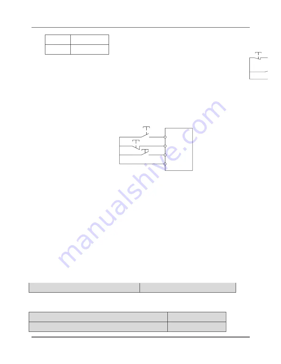
Fig. 6-19 Three-wire operation mode 1
3:
Three-wire operation mode
i=3
,
4
,
5
,
6
Fig. 6-20 Three-wire operation mode 2
In Fig.6-19 and 8-20, X1 is defined as running FWD, X2 is defined as running
REV, and K is used for selecting running direction;
In Fig. 6-19 and 8-20, STOP is a normally closed button for stopping the
motor. RUN, FWD and REV are normally open buttons for running the motor, and
they are active at pulse edge.
In Fig. 6-19 and 8-20, Xi (I=3~7) is defined as three-wire running control
terminal of X3~X7.
In 3-wire mode, when X3~X7 is not selected, the inverter will report ERR4
fault.
P6.01 Up/down rate
Setting range:0.10
~
99.99Hz/s
Up/down rate: To define the increase/decrease rate when using up/down
terminal to change reference frequency.
P6.02 Selecting the function of control terminal X1 Setting range: 0~30
P6.03 Selecting the function of control terminal X2 Setting range:0
~
30
0
FWD
1
REV
STOP
RUN
K
FWD
Xi
REV
COM
FWD
X1(FWD)
Xi
X2(REV)
COM
STOP
REV