


TMP High Performance Vector Control Inverter User Manual
73
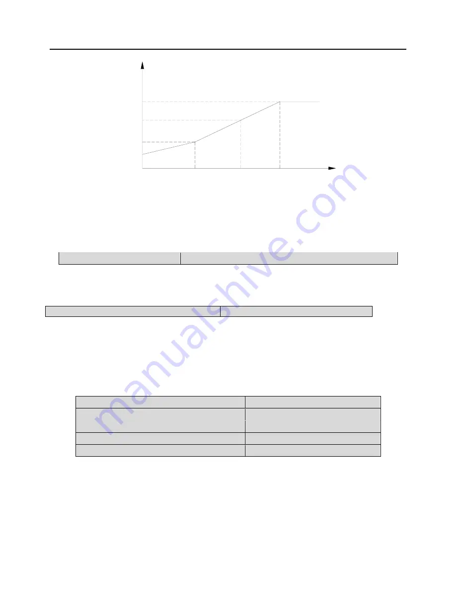
output
voltage
VN
Output
frequency
P4.04
0
P4.05
P4.06
F
P4.03
P4.07
BASE
Fig. 6-13 Torque boost
Note:
Generally, factory setting (2%) can satisfy most applications. If over-current fault occurs
during startup, please increase this parameter from zero gradually until it meets requirement. Pay
attention that large torque boost could damage equipment.
P4.08 Slip compensation
Setting range
:
0.0
~
10%(Rated speed P3.04)
In V/F control mode, motor's speed will be decreased with load rising. In order to ensure
the motor's speed be close to synchronous speed in rated load condition, slip compensation can be
done according to the preset frequency.
P4.09 AVR function
Setting range: 0, 1
0: Disabled;
1: Enabled
AVR is auto voltage regulation. When the inverter's input voltage differs with the rated input
voltage, the inverter's output voltage can be stablized by adjusting the width of PWM wave.
This function is disabled when the output voltage is higher than input voltage.
P5 Vector control funtion
P5.00 ASR proportional gain 1
Setting range:0.00
~
10.00
P5.01 ASR integration time 1
Setting range:0.00
~
10.00
P5.02 ASR proportional gain 2
Setting range:0.00
~
10.00
P5.03 ASR integration time 2
Setting range:0.00
~
10.00
P5.04 ASR switching frequency
Setting range:0.0
~
99.99Hz
Through P5.00~P5.04, user can set the proportional gain P and integration time I of speed
regulator, so as to change the speed response characteristic.
a.
Speed regulator (ASR)'s structure is shown in Fig.6-14, where K
P
is proportional gain P,
and K
I
is integration time I.