Electrical Maintenance
86
5. Disconnect the three wires from the phase
select module at the motor contactor.
6. Unplug the phase select module harness.
7. Remove the old phase select module.
8. Install the new phase select module.
9. (3 Phase Applications) Connect the new phase
select module wires to the lower contactor
(MCA) as follows:
Connect the Brown wire to L1 on the
contactor.
Connect the Gray wire to L2 on the contactor.
Connect the Black wire to L3 on the contactor.
Use crimp-on terminals as required.
10. (Single Phase Applications) Connect the new
phase select module wires to the lower
contactor (MCA) as follows:
Connect the Brown wire to L1 on the
contactor.
Connect the Gray wire to L2 on the contactor.
Use crimp-on terminals as required.
Tape the Black wire back onto itself. It is not
used on single-phase installations.
11. Connect the plug on the short harness from the
phase select module.
12. Install the high voltage cover.
13. Secure wires and wire harnesses as required
using cable ties.
14. Connect the unit battery.
15. Perform a Pretrip Test to verify proper
operation.
Diagnostics
1. Plug the standby power cord into a know good
power supply and turn the unit on.
2. Using a Fluke Meter, test the L1, L2, and L3
circuits at the input to the terminals where the
Brown, Blue and Black wires are connected.
The voltage should be between 200-480 VAC
between the circuits. If not, repair as necessary
to supply the needed voltage to the unit.
3. Check the 8 circuit to the phase select module
for 12 Vdc. If voltage is not present, check the
phase select module connector and the
interface board connector for secure
connections.
4. If correct AC power is present in step 2 above,
then the ER output should measure 12 Vdc. If
no voltage is present, replace the phase select
module.
5. If voltage is present on the ER output, then
LED 7 (K5 Diesel/Electric Relay) on the
interface board should be on. If not, check the
K5 Diesel/Electric Relay circuit on the
interface board.
6. If voltage is measured on the ER output, and
LED 7 is on, then the 7EA input should
measure 12 Vdc. If voltage is not present,
check the phase select module connector and
the interface board connector for secure
connections.
7. If voltage is present on the ER output and the
7EA input, and LED 7 is on, then either the
7EB or 7EC output should measure 12 Vdc
and one of the phase select contactors should
be on. If voltage is not present on either the
7EB or 7EC output, replace the phase select
module.
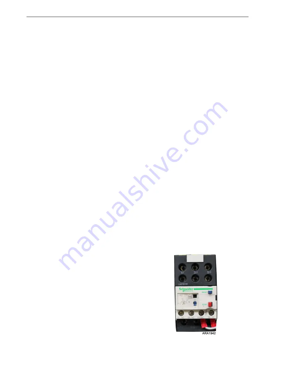
Overload Relay
The overload relay protects the standby electric
motor. It is located in the high voltage box. The
overload relay opens the circuit to the electric
motor if the current exceeds the overload relay
setting. The overload relay resets automatically.
Figure 153: Typical Overload Relay
Summary of Contents for UT-1200
Page 10: ...Table of Contents 10...
Page 20: ...Safety Precautions 20...
Page 76: ...Operating Instructions for Premium HMI Control Panel 76...
Page 88: ...Electrical Maintenance 88...
Page 98: ...Engine Maintenance 98 Figure 167 Fuel Components...
Page 142: ...Refrigeration Service Procedures 142...
Page 148: ...Clutch Maintenance 148...
Page 150: ...Structural Maintenance 150...
Page 162: ...Wiring and Schematic Diagrams Index 162...
Page 163: ...163 Schematic Diagram Page 1 of 2...
Page 164: ...164 Schematic Diagram Page 2 of 2...
Page 165: ...165 Wiring Diagram Page 1 of 5...
Page 166: ...166 Wiring Diagram Page 2 of 5...
Page 167: ...167 Wiring Diagram Page 3 of 5...
Page 168: ...168 Wiring Diagram Page 4 of 5...
Page 169: ...169 Wiring Diagram Page 5 of 5...


