Service Guide
11
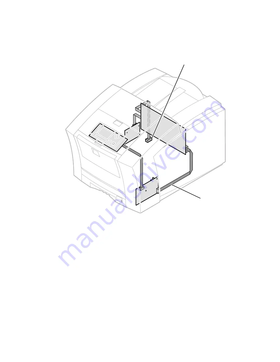
An internal data bus, called the I
2
C bus, connects all I/O boards to the main
board. Through this single bus, the main board can “poll” the I/O boards for the
state of the printer’s sensors as well as actuate the printer’s solenoids. This data
bus greatly simplifies the wiring that would otherwise be required for monitoring
numerous sensors and solenoids. The I
2
C bus also extends down to the High-
capacity Paper Trays.
The printer’s I
2
C bus
0388-05
I
2
C bus
High-capacity
Paper Tray
connection
Summary of Contents for Phaser 840
Page 11: ...xii Phaser 840 and 850 Color Printers ...
Page 65: ...54 Phaser 840 and 850 Color Printers ...
Page 101: ...90 Phaser 840 and 850 Color Printers ...
Page 125: ...114 Phaser 840 and 850 Color Printers ...
Page 134: ...Service Guide 123 Clearing PostScript NVRAM menu item ...
Page 135: ...124 Phaser 840 and 850 Color Printers ...
Page 166: ...Service Guide 155 Figure 1 Cabinet FRUs 7 5 6 8 1 2 4 0388 21 3 9 9 ...
Page 170: ...Service Guide 159 Figure 3 Paper path FRUs 0388 80 2 1 5 11 10 9 12 6 4 3 7 13 8 11a 11b ...
Page 172: ...Service Guide 161 Figure 4 Motor and fan FRUs 0388 14 7 4 3 5 6 2 1 ...
Page 174: ...Service Guide 163 Figure 5 Circuit board FRUs 4 3 5 2 1 9 7 6 8 10 11 13 0388 81 12 7a ...
Page 176: ...Service Guide 165 Figure 6 Solenoid and clutch FRUs 4 5 3 2 1 0388 23 ...
Page 182: ...Service Guide 171 Figure 9 High capacity PaperTray 0388 65a 1 2 ...


