Service Guide
9
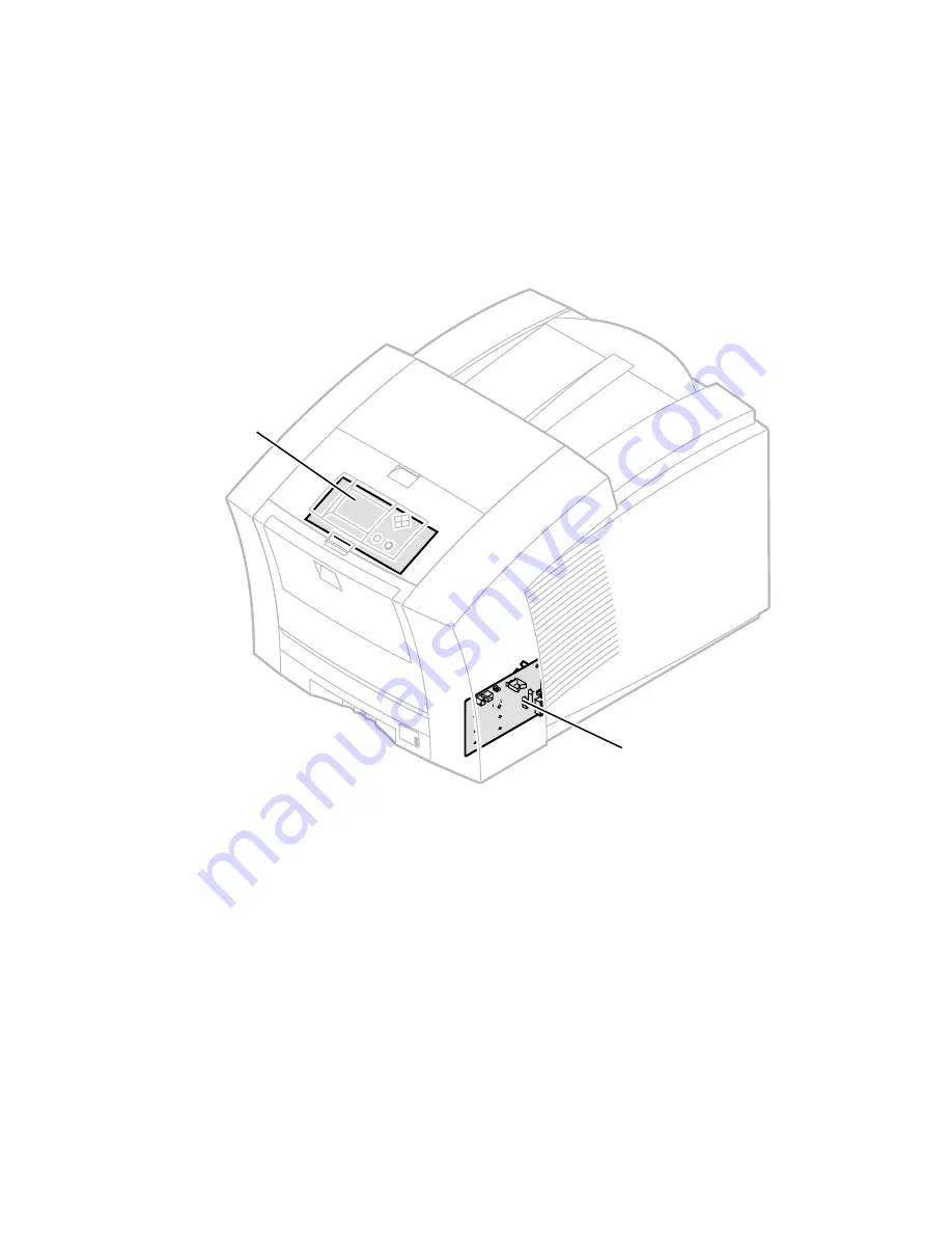
Seven circuit boards support the printer’s electronics. Two boards, called I/
O boards (left and right), support the front panel, solenoids and sensors. The
main board contains the printer’s CPU processor, RAM and ROM. The power
control board distributes power supply voltages to the other printer boards and
many of the printer motors. The power supply converts the AC line voltage into
internal AC and DC voltages. The front panel provides a user interface to the
printer. The printhead drive board, a part of the printhead, manages the signals
and voltages of the printhead’s printing elements and sensors. The optional
network card and internal hard drive could be considered eight and ninth circuit
boards.
Circuit boards of the print engine (right front view)
0388-03
I/O board
right
Front
panel
Summary of Contents for Phaser 840
Page 11: ...xii Phaser 840 and 850 Color Printers ...
Page 65: ...54 Phaser 840 and 850 Color Printers ...
Page 101: ...90 Phaser 840 and 850 Color Printers ...
Page 125: ...114 Phaser 840 and 850 Color Printers ...
Page 134: ...Service Guide 123 Clearing PostScript NVRAM menu item ...
Page 135: ...124 Phaser 840 and 850 Color Printers ...
Page 166: ...Service Guide 155 Figure 1 Cabinet FRUs 7 5 6 8 1 2 4 0388 21 3 9 9 ...
Page 170: ...Service Guide 159 Figure 3 Paper path FRUs 0388 80 2 1 5 11 10 9 12 6 4 3 7 13 8 11a 11b ...
Page 172: ...Service Guide 161 Figure 4 Motor and fan FRUs 0388 14 7 4 3 5 6 2 1 ...
Page 174: ...Service Guide 163 Figure 5 Circuit board FRUs 4 3 5 2 1 9 7 6 8 10 11 13 0388 81 12 7a ...
Page 176: ...Service Guide 165 Figure 6 Solenoid and clutch FRUs 4 5 3 2 1 0388 23 ...
Page 182: ...Service Guide 171 Figure 9 High capacity PaperTray 0388 65a 1 2 ...


