Service Guide
103
7.
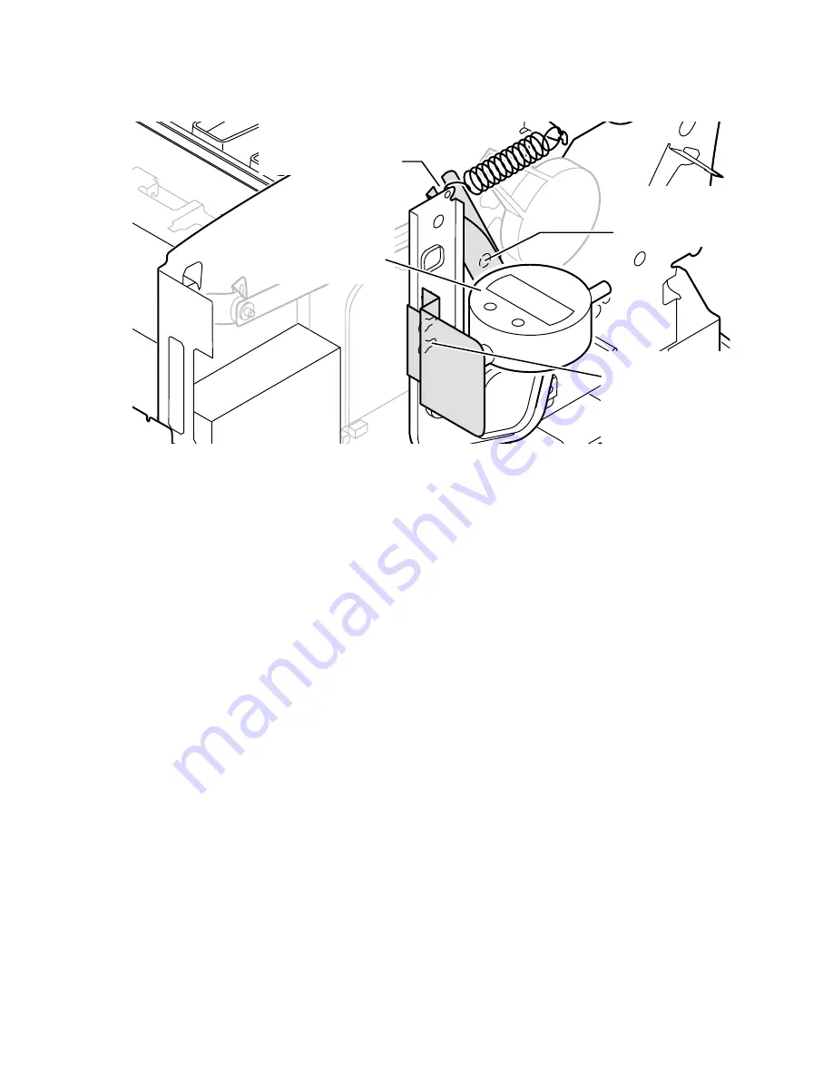
Install the digital gap indicator and bracket to the left side of the printer
frame and tilt arm. Ensure the digital indicator is set to inches, “in.”
Press Origin to zero the digital indicator.
8.
At the right side of the printhead, insert the RIGHT printhead spacer
between the printhead and the drum. Check the indicator; for a “hot
adjustment” it should read 0.0070
+
/
-
0.0010 inches, and 0.0030
+
/
-
0.0010 inches for a “cold” adjustment. Adjust the printhead’s spacing
adjustment screws until the indicator reads the correct value.
Attaching the digital gap indicator
0388-31
0388-36
Secure indicator
in place with screw
provided in frame
Attach bracket
in forward most
position to tilt
arm. Ensure a
flush fit.
Place indicator
bracket over
hex-screw
Attach digital gap
indicator to side
frame
Summary of Contents for Phaser 840
Page 11: ...xii Phaser 840 and 850 Color Printers ...
Page 65: ...54 Phaser 840 and 850 Color Printers ...
Page 101: ...90 Phaser 840 and 850 Color Printers ...
Page 125: ...114 Phaser 840 and 850 Color Printers ...
Page 134: ...Service Guide 123 Clearing PostScript NVRAM menu item ...
Page 135: ...124 Phaser 840 and 850 Color Printers ...
Page 166: ...Service Guide 155 Figure 1 Cabinet FRUs 7 5 6 8 1 2 4 0388 21 3 9 9 ...
Page 170: ...Service Guide 159 Figure 3 Paper path FRUs 0388 80 2 1 5 11 10 9 12 6 4 3 7 13 8 11a 11b ...
Page 172: ...Service Guide 161 Figure 4 Motor and fan FRUs 0388 14 7 4 3 5 6 2 1 ...
Page 174: ...Service Guide 163 Figure 5 Circuit board FRUs 4 3 5 2 1 9 7 6 8 10 11 13 0388 81 12 7a ...
Page 176: ...Service Guide 165 Figure 6 Solenoid and clutch FRUs 4 5 3 2 1 0388 23 ...
Page 182: ...Service Guide 171 Figure 9 High capacity PaperTray 0388 65a 1 2 ...


