Service Guide
131
7.
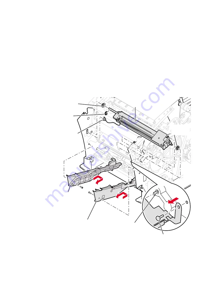
Remove the left and right maintenance drawer guides. Each is held in
place by a single screw at the front and two frame latches at the rear.
Note
If you have trouble removing the right maintenance drawer guide,
manually rotate the x-axis drive to move the printhead (in its
forward position) to the center of its travel.
8.
Remove the screw securing the right side of the upper feed-roller
assembly to the inside of the printer frame.
9.
Disconnect the wiring harness leading from the upper feed-roller
assembly to the inside the left side of the printer frame.
10.
Remove the C-clip located on the left-inside printer frame securing the
upper feed-roller assembly in place.
11.
Remove the upper feed-roller assembly. Separate the assembly into its
two halves.
Removing the upper feed roller assembly (front)
Keyed
bushing
840-4-14
Right
maintenance
drawer guide
Left
maintenance
drawer guide
Wiring
harness
C-clip
Upper feed-roller
assembly
Keyed
bushing
Remove
screw from
right side
Key pin
on right
frame aligns
upper feedroller
assembly
Summary of Contents for Phaser 840
Page 11: ...xii Phaser 840 and 850 Color Printers ...
Page 65: ...54 Phaser 840 and 850 Color Printers ...
Page 101: ...90 Phaser 840 and 850 Color Printers ...
Page 125: ...114 Phaser 840 and 850 Color Printers ...
Page 134: ...Service Guide 123 Clearing PostScript NVRAM menu item ...
Page 135: ...124 Phaser 840 and 850 Color Printers ...
Page 166: ...Service Guide 155 Figure 1 Cabinet FRUs 7 5 6 8 1 2 4 0388 21 3 9 9 ...
Page 170: ...Service Guide 159 Figure 3 Paper path FRUs 0388 80 2 1 5 11 10 9 12 6 4 3 7 13 8 11a 11b ...
Page 172: ...Service Guide 161 Figure 4 Motor and fan FRUs 0388 14 7 4 3 5 6 2 1 ...
Page 174: ...Service Guide 163 Figure 5 Circuit board FRUs 4 3 5 2 1 9 7 6 8 10 11 13 0388 81 12 7a ...
Page 176: ...Service Guide 165 Figure 6 Solenoid and clutch FRUs 4 5 3 2 1 0388 23 ...
Page 182: ...Service Guide 171 Figure 9 High capacity PaperTray 0388 65a 1 2 ...


