8. Electronic System
2004-10
Technical Manual for sunrise RC, TW, TS, TC, BC, 6F No. T 137 302 Rev No. 1.1
8-15
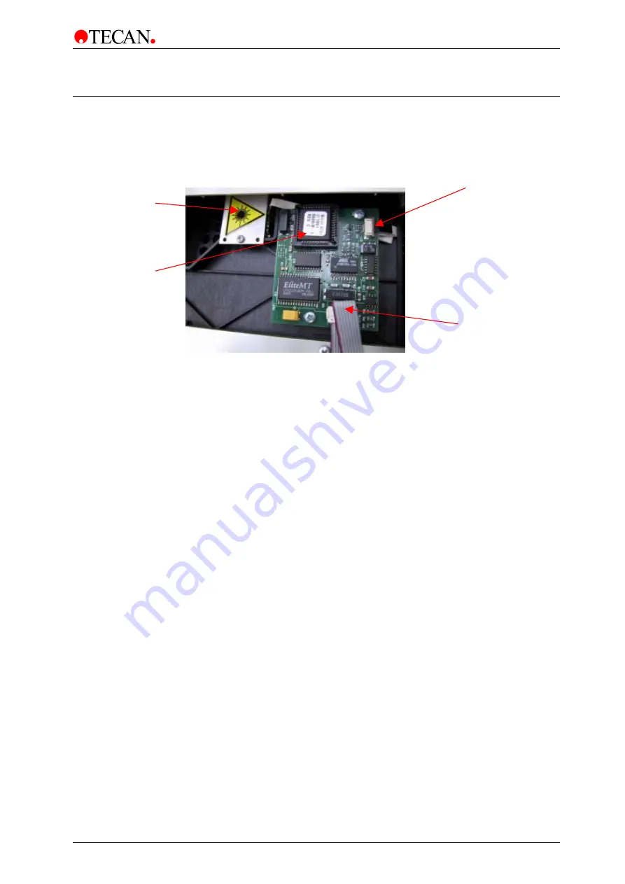
8.14 Barcode Board
This board controls the barcode reader.
Connector to Barcode scanner
Connetion to cpu board
(option cable)
Boot EPROM
Laser Scanner
The power supply unit is replaced using the following procedure:
1. Switch the instrument OFF.
2. Remove the main power cable from the socket.
3. Remove the instrument top cover.
4. Remove the Epack top cover.
5. Remove the front cover of the instrument.
6. Unscrew the barcode board.
7. Replace the complete mirror..
8. Replace all Parts in reverse order.


