background image


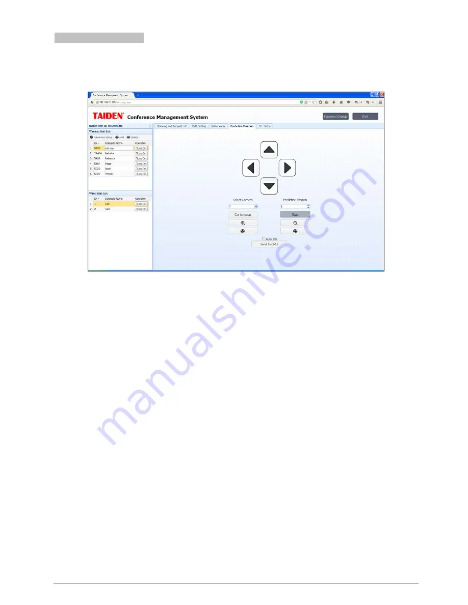
5.2.5 Predefined position 

If the conference system is equipped with cameras, the system can carry out automatic video tracking, i.e. display the 

image of the speaking participator to the display devices (large screen, TV, and so on). Predefine position is to set the 

predefined position of each microphone. 


Figure 5.8    Predefine Position 


Microphone predefined position setup: 

1

  Select a microphone on the speaking list, then click the “Camera Ctrl” button to open the “Predefine Position” 

interface; 

2

  Select the proper camera in the Select Camera combo box (since each conference can be equipped with 

multiple cameras, the operator shall select the proper camera to give the best image of each participator); 

3

  Select the predefine position number (each camera can accommodate 64 positions); 

4

  Adjust the camera angle by the four direction buttons, and click zoom in/out button to adjust the size of the 

video image; 

5

  Click the “Send to CMU” button to send the current predefined position to the CMU if the adjustment is done; 

6

  Repeat the above steps to set the predefined position for other seats/microphones; 

During the conference, if all microphones are configured with predefined positions, the camera will aim at the speaking 

participator automatically (when video tracking setting in menu of main unit is “turn on”), i.e. automatic video tracking. 

Note:   

When connect to HCS-3316HDB without matrix, please set the “Select Camera” to be 1; 

If the camera features auto iris, you can select “Auto Iris” to be applied for all predefined positions. If “Auto Iris” option is 

checked, then all predefined positions will use auto iris; if not checked, the iris for each predefined position can be 

adjusted and saved respectively. 


Panorama setup: 

select proper camera and predefine position number, then adjust the camera angle by the four 

direction buttons, and click zoom in/out button to adjust the size of the video image, at last, click the “Send to CMU” 

button to save the panorama if the adjustment is done.


79 

Summary of Contents for HCS-5300MA/80

Page 1: ...New Generation Digital Infrared Wireless Conference System Installation and Operating Manual V 2 8...

Page 2: ...f the European directive 2014 30 EU To protect your hearing avoid high pressure level on earphones Adjust to a lower and convenient level If any detailed information needed please contact your local a...

Page 3: ...r plug is damaged liquid has been spilled or objects have fallen into the apparatus the apparatus has been exposed to rain or moisture does not operate normally or has been dropped 17 Do not place the...

Page 4: ...tch have power supplied to the unit whenever the power cord is inserted into the power source however the unit is operational only when the ON OFF switch is in the ON position The power cord is the ma...

Page 5: ...rode the battery and cause fire explosion leakage or heat generation Be careful to put the battery into the charging case with correct electrode position otherwise it may cause fire explosion leakage...

Page 6: ...ions and indications 11 2 3 Installation 13 2 4 Connection 14 2 4 1 To interpretation devices 14 2 4 2 To other auxiliary devices 14 2 4 3 To HCS 8300MI series 15 2 4 4 System connection 1 16 2 4 5 Sy...

Page 7: ...6 USB Audio 37 2 6 1 Installation of USB Audio 37 2 6 2 Digital audio input 38 2 6 3 Digital audio output 39 Chapter 3 Digital infrared transceiver 40 3 1 Overview 40 3 2 Functions and indications 41...

Page 8: ...3 Charging device 87 6 4 Power adapter 87 6 5 Dedicated extension cable for digital infrared transceiver 88 6 6 HCS 5300TZJ2 transceiver stand 88 6 7 Earphones 89 Chapter 7 Fault diagnosis 90 7 1 Digi...

Page 9: ...8 14 Display language list 103 Appendix 104 Dedicated 6 PIN Extension Cable 104 VIII...

Page 10: ...of new generation digital infrared wireless conference main unit Chapter 3 Digital infrared transceiver Detailed description of functions position planning installation and connection of digital infra...

Page 11: ...pter Digital IR Wireless Conference Unit HCS 5300CE 80 Digital IR Wireless Chairman Unit 5 voting keys 1 7 CHs English panel HCS 5300DE 80 Digital IR Wireless Delegate Unit 5 voting keys 1 7 CHs Engli...

Page 12: ...e CMP CBL5300 10CMP 10 m Dedicated Transceiver Cable CMP CBL5300 20CMP 20 m Dedicated Transceiver Cable CMP CBL5300 30CMP 30 m Dedicated Transceiver Cable CMP CBL5300 40CMP 40 m Dedicated Transceiver...

Page 13: ...as well as for permanent installations The flexibility of the wireless chairman and delegate units allows easy arrangements of various conferences The system consists of one digital infrared wireless...

Page 14: ...Digital IR Wireless Delegate Unit 5 voting keys 1 7 CHs English panel HCS 5301D 80 Digital IR Wireless Delegate Unit 1 7 CHs 2 channel selectors dual predefined positions HCS 5302C 80 Digital IR Wire...

Page 15: ...ble CMP CBL5300 40CMP 40 m Dedicated Transceiver Cable CMP CBL5300 50CMP 50 m Dedicated Transceiver Cable CMP Tripod HCS 5300TZJ2 Transceiver stand Earphones EP 820AS Single Earphone TRS connector Rin...

Page 16: ...radio interference inherent to radio wave based wireless communications No radio radiation No radio frequency license needed for operating an infrared system all over the world Adapts 1 to 8 MHz tran...

Page 17: ...ed light Infrared radiation is part of the electro magnetic spectrum which is composed of visible light radio waves and other types of radiation Its wavelength is longer in comparison with the wavelen...

Page 18: ...dered For outdoor using a site test will be required to determine the needed amount of transceivers With sufficient transceivers perfect signal transmission can be fulfilled even in bright sunlight 1...

Page 19: ...ess conference unit gets best sensitivity when it directly faces a transceiver Every HCS 5300 80 series new generation digital infrared wireless conference unit is equipped with infrared glass at its...

Page 20: ...plane determined by the position of the infrared wireless conference unit The size and the position of the coverage area are related to the height chosen for mounting the transceiver If infrared signa...

Page 21: ...an the required intensity Figure 1 8 Increased coverage area caused by added radiation power However due to the differences in the delays of the signals from two or more transceivers the signals may c...

Page 22: ...e maximal number of wireless conference units is 1000 With connecting to the HCS 8300MES extension unit the maximal number of wired conference units is 200 Four microphones of digital infrared wireles...

Page 23: ...ont panel of HCS 5300M 80 main unit Rear panel of HCS 5300MA 80 main unit Rear panel of HCS 5300MB 80 main unit Rear panel of HCS 5300MC 80 main unit Figure 2 1 New generation digital infrared wireles...

Page 24: ...2 Menu display 256 32 LCD displays main unit status and configuration menu 13 Monitoring earphone interface Earphone jack 3 5 mm Backside 14 Ethernet For communication between the conference main unit...

Page 25: ...the brackets with these screws and put the main unit in the cabinet Finally fix the four holes up with screws see Figure 2 2 Figure 2 2 Installation of new generation digital infrared wireless confere...

Page 26: ...preter s unit interface and fulfill eight channels simultaneous interpretation including floor audio Figure 2 4 Main unit connecting to HCS 4385U 50 through interpreter s unit interface 2 4 2 To other...

Page 27: ...connecting to PA 2 4 3 To HCS 8300MI series HCS 5300M main unit connects with HCS 8300MI series 8 Channels Audio Input Interface to realize the following function a Transmits 7 digital AES EBU analog...

Page 28: ...d on large screen or other display devices The automatic video tracking system is compatible with several kinds of video signals and operates automatic video switching The video tracking s ystem is co...

Page 29: ...d TAIDEN HCS 6100 network central control system can be joined together seamlessly It can link together various devices hardware and environment equipment from different manufacturers The central cont...

Page 30: ...Figure 2 10 System connection Wired wireless discussion digital simultaneous interpretation video tracking central control 18...

Page 31: ...and TAIDEN HCS 6100 network central control system can be joined together seamlessly It can link together various devices hardware and environment equipment from different manufacturers The central co...

Page 32: ...Figure 2 11 System connection Wireless discussion video tracking central control 20...

Page 33: ...At this point only 6 transceivers can be supported if you want to connect more transceivers please connect them via a HCS 5300MX The maximal number of wired units that can be directly connected to th...

Page 34: ...ill be switched off first automatically first in first out If the total number of active microphone is less than 4 in the system the chairman unit can be activated till the number reaches 4 and then i...

Page 35: ...signal will be null when Mic IR Automatic Adjusting is set No b Microphone Battery Status Use the button to select Microphone Battery Status and use the MENU button to confirm The ID voltage and resid...

Page 36: ...hannels for all Interpreter units in one booth is uniform After setup of booth numbers the user interface to set up output channel A B C language will show for each booth 1 Set up channel A language f...

Page 37: ...output channel when the microphone of interpreter unit is available 1 Press the button to select Enable or Disable 2 Press the MENU to save and then go to step h h Interp Units Green LED Enable disab...

Page 38: ...Auto Att Attenuation Setting If a headphone is plugged howling may happen when the microphone is activated Headphone auto att function is used to suppress howling for floor language channel If enabled...

Page 39: ...etup 3 Microphone Treble Setting The same chronological order as for Microphone Gain Setting setup 4 Microphone Low Cut Setting a Press the button to select On or Off b Press the MENU button to save a...

Page 40: ...and Gateway The same chronological order as for the IP address set up 2 5 15 Time Setting Set system clock a Press the MENU button to go to Year Month Day Hour Minute in turn b Press the button to se...

Page 41: ...ress the button to select Yes or No b Press the MENU button to save and return to the upper level menu 2 5 20 Parameters Backup Restore The system parameters can be backed up or restored through the f...

Page 42: ...e keys on the wired units one by one to number each unit the button indicating light will be deactivated c Once all units are numbered restart the CMU to update the number information Interpreter Unit...

Page 43: ...ar end C LineOut1 output feature the sum signal of Dante In2 LineIn1 LineIn2 active microphones D LineOut2 and floor audio output feature each the sum signal of Dante In LineIn1 LineIn2 active microph...

Page 44: ...Figure 2 13 Audio mode setting Normal Mode Figure 2 14 Audio mode setting Remote Conferencing Mode1 32...

Page 45: ...Figure 2 15 Audio mode setting Remote Conferencing Mode2 Figure 2 16 Audio mode setting External Process Mode1 33...

Page 46: ...Figure 2 17 Audio mode setting External Process Mode2 34...

Page 47: ...nels LINE OUT 6 SI CHs Dante output the signals of LINE OUT1 LINE OUT2 0 to 5 SI channels b Press the MENU button to save and return to the upper level menu 2 5 30 Set RS 232 Baudrate Set the baudrate...

Page 48: ...the STANDBY button to enter power management interface as shown as the following figure a Press the button to select Power Off or Setting If Power Off is selected the main unit switches to standby mo...

Page 49: ...to introduce the function and operation of the USB Audio 2 6 1 Installation of USB Audio Once the HCS 5300M main unit connects to the computer the HCS 5300M USB Audio will be detected and activated a...

Page 50: ...following figure Figurer2 19 Adjusting microphone volume Note To avoid feedback only the output floor audio except audio of PC of the main unit will be recorded Too high volume may lead to distortion...

Page 51: ...fy its setting in the Playback dialog box as shown in the following figure Figurer2 20 Adjusting playback volume Note Please select the HCS 5300M USB Audio as the current device on playback Usually HC...

Page 52: ...tripod at any appropriate spot Types HCS 5300TD 80 Digital Infrared Transceiver ceiling wall or tripod mounted suitable for less than 6 m height HCS 5300TDS 80 Digital Infrared Transceiver suspension...

Page 53: ...2 meter 6 PIN cable CBL 5300 2 Power indicating light 3 Switchers for radiation area selection 4 Power adapter port connect to HCS ADP24V Note The HCS 5300TDS 80 digital infrared transceiver has four...

Page 54: ...infrared cable splitter with one input and four outputs that can be used to connect four transceivers receivers at most Figure 3 2 HCS 5352 cable splitter Figure 3 2 1 To the transceiver interface of...

Page 55: ...of the transceivers and the length of the cable connected in the system Figure 3 3 Service area of HCS 5300 80 digital infrared transceivers and receiver Type No Mounting height H Coverage area radius...

Page 56: ...s good anti interference performance to ambient light the distance of the transceiver receiver from lighting equipment must be at least 50 cm to guarantee adequate intensity and stability of infrared...

Page 57: ...signals blocking So each transmitter should communicate with more than one receiver to avoid blocking 3 4 1 5 Stay away from plasma displays When planning an infrared wireless discussion system plasm...

Page 58: ...and make sure that they can cover the system operating area Figure 3 10 Two transceivers cannot cover the whole operating area Apparently only two transceivers cannot cover the system operating area c...

Page 59: ...are within the circular coverage area of one single transceiver However to avoid blocking communication two or more transceivers are indicated Figure 3 13 Planning the transceiver round table arrange...

Page 60: ...venly as shown in Figure 3 14 transceiver No 1 could only communicate with the few conference units in the last row left row in Figure 3 16 compared to the transceiver placed over the front row The re...

Page 61: ...signals from more than one transceiver As described in section 1 4 5 overlap effect or multipath effect will occur the intensity of the receiving signals is enhanced if the two signals have the same p...

Page 62: ...splitter must be connected to the main unit directly and the cable lengths to different rooms do not need to be equal as shown in figure 3 21 All cable lengths B1 must be equal All cable lengths B2 m...

Page 63: ...ounted Mounting steps Step 1 Install the ceiling mounting kit at the top of the HCS 5300TD 80 Transceiver Step 2 Drill a hole with 98 mm diameter into the ceiling for mounting and heat elimination dur...

Page 64: ...ation of the HCS 5300TD 80 and mark the positions of the drilling holes Drill two holes 5 mm diameter 30 mm depth into the ceiling Step 2 Put the included rubber plugs into the mounting holes on the c...

Page 65: ...5300TD 80 digital infrared transceiver tripod mounted Mounting steps Step 1 Fix the HCS 5300TD 80 digital infrared transceiver onto the wall mounted bracket with M3 screws Step 2 Fix the tripod mount...

Page 66: ...ared transceiver tripod mounted Mounting steps Step 1 Put the bracket on the bottom of the transceiver and fix it with rotation Step 2 Aim the mounting hole at the bottom of HCS 5300TD 80 digital infr...

Page 67: ...d bracket with M3 screws Step 2 Position the wall mounted bracket on the wall according to the installation location of the HCS 5300TD 80 and mark the positions of the drilling holes Drill four holes...

Page 68: ...ounting steps Step 1 Fix M6 60 hook up riveting bolt onto the hard ceiling such as concrete ceiling Step 2 Fix HCS 5300TDS 80 digital infrared transceiver onto the suspension with M3 12 screws Step 3...

Page 69: ...Figure 3 28 Requirements of user customized suspension 57...

Page 70: ...unting steps Step 1 Install the ceiling mounting kit at the top of the HCS 5300TH 80 Transceiver Step 2 Drill a hole with 98 mm diameter into the ceiling for mounting and heat elimination during opera...

Page 71: ...5300TH 80 digital infrared transceiver tripod mounted Mounting steps Step 1 Fix the HCS 5300TH 80 digital infrared transceiver onto the wall mounted bracket with M3 screws Step 2 Fix the tripod mount...

Page 72: ...acket with M3 screws Step 2 Position the wall mounted bracket on the wall according to the installation location of the HCS 5300TH 80 and mark the positions of the drilling holes Drill four holes 5 mm...

Page 73: ...5300TW 80 digital infrared transceiver wall mounted Mounting steps Step 1 Drill two holes 5 mm diameter 30 mm depth and 100 6 mm interval into the wall Step 2 Put the included rubber plugs and the M3...

Page 74: ...3 33 Figure 3 33 Digital infrared transceiver connecting to digital infrared wireless conference main unit Note The correctness of the cable connection can be ascertained if the indicating light on th...

Page 75: ...t type used Functions include listen speak LCD display key press sign in vote simultaneous interpretation etc Types HCS 5300CE 80 Digital IR Wireless Chairman Unit 5 voting keys 1 7 CHs English panel...

Page 76: ...ating HCS 5300CE 80 HCS 5300DE 80 HCS 5302D 80 HCS 5302C 80 HCS 5301D 80 Bottom side Left side functions for 5301D 80 only Right side Figure 4 1 HCS 5300 80 series new generation digital infrared wire...

Page 77: ...pressing this button will emit a ring tone 9 5 Multifunctional buttons with indicator around Sign in Candidate 1 Response ATTEND 1 a In sign in mode sign in indicating light will blink press this but...

Page 78: ...tton to vote for candidate 5 b In audience response rating state of voting mode voting indicating light will blink press this button to give a response 100 of 100 10 Dismountable microphone socket 11...

Page 79: ...iver Every HCS 5300 80 series new generation digital infrared wireless conference unit is equipped with infrared glass at its frontage to guarantee maximum receiving angle In the vertical direction th...

Page 80: ...stance between adjacent conference units must be at least 0 5 meter the distance between opposite conference units must be at least 0 8 meter Figure 4 4 Distance between conference units The distance...

Page 81: ...ll the number reaches 4 and then if another chairman microphone is activated the unit switched on first will be switched off first automatically primarily switched off the delegate units and then the...

Page 82: ...interface will be displayed on the LCD on startup including Type Version ID Channel number and language name display interface After startup display the floor audio channel is displayed including Cha...

Page 83: ...airman unit is pressed and return active when the priority button on the chairman unit is released If the priority mode is set as All off in the main unit configuration all active conference units wil...

Page 84: ...UserName is admin and the default password is 123456 the password can be changed after login The default username is administrators that cannot be deleted The login interface is shown in the followin...

Page 85: ...re are two buttons in the right top of the interface Password Change click this button and the below dialog box is shown Input the Old Password New Password and Password Confirm and then click the OK...

Page 86: ...p the Panorama refer to 5 2 5 Add wireless conference units must be added to the Wireless Unit List manually when being connected into the system first or after being deleted Click this button and the...

Page 87: ...n Off turn off the selected microphone Camera Ctrl click this button and set up the camera predefine position on the right side refer to 5 2 5 Type display the type of the conference unit including wi...

Page 88: ...switch off the unit switched on first automatically primarily switched off the delegate units and then the chairman units Voice voice control mode the microphone On Off is controlled by voice particip...

Page 89: ...atically according to the system connection if selecting HCS 3316HDB the input and output cannot be set Select Video Input includes Dome Camera Fixed Camera PC and Other Video Input Output Type includ...

Page 90: ...the setup of the video matrix the video input type will be displayed automatically 2 Assign corresponding output channel by clicking on the cross point of input and output 3 Select Video Track under v...

Page 91: ...he video image 5 Click the Send to CMU button to send the current predefined position to the CMU if the adjustment is done 6 Repeat the above steps to set the predefined position for other seats micro...

Page 92: ...firm Assign now a specific language for each channel After completion click the Send to CMU button to save the settings and to update the conference main unit Booth supports 7 booths at most The syste...

Page 93: ...Note The user defined language only supports a sequence of numbers or letters case sensitive with a maximum of 8 characters the abbreviation supports a maximum of 3 characters 81...

Page 94: ...n 4 EXIT button The LCD displays the corresponding state of input channels and output groups 5 Input channel selectors with indicators 1 4 6 Output group selectors with indicators 1 4 7 Input channels...

Page 95: ...ting rooms 1 Several meeting rooms can be split combined at leisure through the HCS 5300MX Digital IR Conference Room Switcher with CBL5300 cable One HCS 5300MX can combine up to four meeting rooms Fi...

Page 96: ...he HCS 5300MX with CBL5300 cable to connect the transceivers and the HCS 8300MX with 6PIN to RJ45 cable to connect the interpreter units Four meeting rooms can be combined up at most to realize discus...

Page 97: ...nable or Disable c Press the MENU button to save and press EXIT to turn to the upper level menu About Press the button to switch to About and press the MENU button the firmware version of the switcher...

Page 98: ...with the buckles on the right and left side of the battery aiming to the slot 2 Push the battery into the slot tightly according to the arrow direction on the conference unit Figure 6 5 Assemble HCS 5...

Page 99: ...cedure 1 Connect power core 2 Switch on 3 Insert batteries 4 Battery charging indicator lights up LED Status Charging Status Green Fully charged or battery not inserted Red Charging LED off Charging u...

Page 100: ...nector at one end and one female 6P DIN connector at the opposite end Available lengths 5 10 20 30 40 or 50 meters Figure 6 10 CBL5300 dedicated extension cable for digital infrared transceiver 6 6 HC...

Page 101: ...e conference units via an 3 5 mm stereo jack Suitable earphone types include EP 820AS single earphone EP 829 single earphone EP 829SW single earphone HCS 5100PA headphone EP 960BH headphone Any other...

Page 102: ...unit Cannot operate MIC ON OFF button Infrared transceiver is directly under sunshine or spotlight Reposition it and avoid direct sunshine or spotlight Is there any obstacle between the transceiver a...

Page 103: ...into the power socket and supply power to the charging unit The fuse has blown Change the fuse Please contact the local TAIDEN service center The charging indicating light of the charging lattice is n...

Page 104: ...mitted by main unit according to IEC 61603 7 Cabling and system limits Transceiver cable type Specific 6PIN cable HCS 5352 is optional Maximum number of transceivers 4 per output 10 in total HCS 5300M...

Page 105: ...PUT CH 0 7 10 dBu unbalanced RCA jack Maximal number of conference units 1000 units Transceivers I O terminal 6P DIN sockets x 6 External control terminal RS 232C D sub 9 P female USB interface RJ45 E...

Page 106: ...r Wavelength 870 nm Modulation method DQPSK Carrier frequency 1 8 MHz Communication area Area radius from the point underneath the unit Approx 13 m in radius ceiling height 2 5 3 m Approx 11 m in radi...

Page 107: ...frequency 1 8 MHz Communication area Area radius from the point underneath the unit Approx 9 m in radius ceiling height 6 m Approx 11 m in radius ceiling height 9 m Approx 9 m in radius ceiling height...

Page 108: ...nel 2 4 8 MHz Audio channel 3 5 8 MHz Audio channel 4 6 3 MHz Reception Floor audio interpretation audio 0 3 Control signal 2 333 MHz Floor audio interpretation audio 4 7 Control signal 1 666 MHz Acce...

Page 109: ...ht incl battery 0 8 kg Color Silver Charcoal gray Microphone Type Uni directional electret condenser microphone Sensitivity 46 dBV Pa Frequency response 30 20000 Hz Directivity 0 180 20 dB 1kHz Equiva...

Page 110: ...Power consumption 15 W Input interfaces 4 6P DIN sockets Output interfaces 20 6P DIN sockets in 4 groups 5 sockets per group Dimensions Weight 10 6 kg Color White 8 6 Lithium battery Type HCS 5300BAT...

Page 111: ...S 5300BAT batteries LED indicator Power indicator Charging status Green Full charge or battery not inserted Red On charge Dimensions Weight 4 5 kg Color White 8 8 Power adapter Type HCS ADP15V HCS ADP...

Page 112: ...mm Weight 0 3 kg Color Charcoal gray 8 10 CBL 5300 Dedicated extension cable HCS 5300TD TDS 80 dedicated extension cable With one male 6P DIN connector at one end and one female 6P DIN connector at op...

Page 113: ...g EP 829SW Single Earphone Used with the receiver conference unit Hi Fi sound quality 3 5 mm stereo plug 32 Tip and Sleeve Ring NC Frequency response 20 Hz to 20 kHz Sensitivity 108 dBA 1 mW Built in...

Page 114: ...Brown Live Green Yellow Earth Ground Audio cables Chinch connector male Pin Signal Pin GND Earphones 3 5 mm Jack plug Tip Signal left Ring Signal Right Sleeve Electrical earth screen Emergency switch...

Page 115: ...an TIB 80 Romansh ROH 14 Hebrew HEB 47 Turkmen TUK 81 Sanskrit SAN 15 Hungarian HUN 48 Ukrainian UKR 82 Sindhi SND 16 Indonesian IND 49 Vietnamese VIE 83 Sinhalese SIN 17 Italian ITA 50 Cantonese YUE...

Page 116: ...Appendix Dedicated 6 PIN Extension Cable 104...

Page 117: ...Copyright by TAIDEN Last Revision 03 2018 TAIDEN INDUSTRIAL CO LTD 6 F Block B Future Plaza 6060 Qiaoxiang Rd Nanshan District Shenzhen China P C 518053 Website http www taiden com...

Reviews: