4-8
Operating the Inverter
605C Frequency Inverter
Tuning Difficulties
The most important parameter setting for correct operation at low
motor speeds is stator resistance (STATOR RES):
•
Too low
and motor torque will be lower than expected
•
Too high
and the Inverter enters the current limit and will be
unable to ramp-up to speed. Reduce the value of STATOR RES
to eliminate this problem.
See VECTOR FLUXING at menu level 4.
The Start/Stop Mode Explained
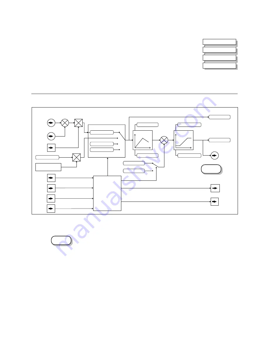
The default configuration below shows the Inverter in Remote control, (using the analog and
digital inputs and outputs). This example will be referred to in the following explanations.
Start/Stop Controlled Remotely
In the configuration shown, the reference value is obtained by summing ANALOG INPUT 1
and ANALOG INPUT 2. The direction of rotation is controlled by DIGITAL INPUT 3. When
the RUN input (DIGITAL INPUT 1) is TRUE, the SPEED DEMAND ramps up to the
reference value at a rate controlled by ACCEL RATE. The Inverter will continue to run at the
reference value while the RUN input remains TRUE.
Similarly when the JOG input (DIGITAL INPUT 5) is TRUE, the SPEED DEMAND ramps up
to the JOG SETPOINT at a ramp rate set by JOG ACCEL RATE (not shown in the diagram).
The Inverter will continue to run at the JOG SETPOINT while the JOG input remains TRUE.
Start/Stop Controlled Locally
The reference value is set by the SETPOINT (LOCAL) parameter. The direction of rotation is
controlled by the DIR key (forward/reverse) on the Operator Station. When the RUN key is
pressed the SPEED DEMAND ramps up to the reference value at a rate controlled by ACCEL
RATE. The Inverter will continue to run at the reference value even when the RUN key is
released. Press the STOP key to “stop” the Inverter.
When the JOG key is pressed and held, the SPEED DEMAND ramps up to the JOG SETPOINT
at a ramp rate set by JOG ACCEL RATE (not shown in the diagram). Release the JOG key to
“stop” the Inverter.
MMI Menu Map
1
SETUP PARAMETERS
2
FUNCTION BLOCKS
3
MOTOR CONTROL
4
VECTOR FLUXING
DEFAULT
SETPOINT
Analog Input 1
Terminal 1
SETPOINT TRIM
Analog Input 2
Terminal 2
RUN
Digital Input 1
Terminal 20
TRIP RESET
Digital Input 2
Terminal 21
DIRECTION
Digital Input 3
Terminal 22
JOG
Digital Input 5
Terminal 24
+
-
+
-
MAX SPEED CLAMP
MIN SPEED CLAMP
System Ramp
Clamps
DECEL RATE
ACCEL RATE
Sequencing Logic
Reference Selection
SETPOINT(REMOTE)
LOCAL SETPOINT
JOG SETPOINT
0%
HEALTH
Digital Output 1
Terminal 12, 13
RUNNING
Digital Output 2
Terminal 14, 15
RAMP OUTPUT
Analog Output 1
Terminal 7
+
+
SPEED TRIM
SPEED DEMAND
FORWARD/REVERSE
Key on Operator Station
+
-
SPEED SETPOINT
0%
Selected with
REMOTE SETPOINT
EXTERNAL
TRIP
Digital Input 4
Terminal 23
Figure 4-6 Portion of the Default Configuration
DEFAULT
Summary of Contents for 605C
Page 16: ...1 4 Getting Started 605C Frequency Inverter ...
Page 22: ...2 6 An Overview of the Inverter 605C Frequency Inverter ...
Page 50: ...4 14 Operating the Inverter 605C Frequency Inverter ...
Page 66: ...5 16 The Operator Station 605C Frequency Inverter ...
Page 156: ...8 2 Routine Maintenance and Repair 605C Frequency Inverter ...
Page 184: ...10 22 Parameter Specification 605C Frequency Inverter ...
Page 212: ...13 6 Application Notes 605C Frequency Inverter ...
Page 214: ...14 2 Serial Communications 605C Frequency Inverter ...
Page 236: ......


