background image

2-8

BKS-R3219A/R1617A I&SSM

2-10-2. How to Attach the Key Label

Attach the key labels to the buttons with the following
procedure.

Required tool

Key-cap puller: Part number 3-179-054-02

1.

Remove the button by inserting the tips of the tool in
the grooves along the sides of the button.

2.

Remove the internal cap by holding the grooves of the
internal cap in the removed button with the tips of the
tool and slightly bending the internal cap.

3.

Attach a key label and install the internal cap.

4.

Install the button in the original location.

Key-cap puller

Key-cap puller

2-11. Settings by Using the Buttons

(Setup Function)

2-11-1. Setting the Station Number

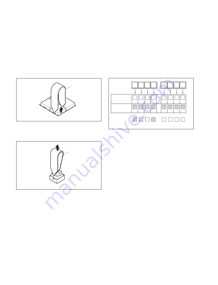
Set the station number using the source/destination select
buttons 1 to 8. The station number is obtained by adding
the binary place values of the buttons that are lit. For
example, if the buttons 1, 2 and 4 are lit as shown below,
the station number is 11 (= 1 

+

 2 

+

 8).

n

Do not assign the same number to more than one unit in a
routing system.

1.

Press and hold the LOCK (CHOP) and PROT buttons
for about 5 seconds to reset the software.

2.

Press and hold the source/destination select buttons 1,
2, 3, and 4 during being rebooted to enter station
number setting mode.

n

When the power is turned ON for the first time, station
number setting mode is automatically set, and steps 1
and 2 are not required.

3.

Press the appropriate source/destination select buttons
so that the desired station number is obtained.

4.

Press the LOCK (CHOP) button.
The set station number is registered.

0

0

0

0

0

0

0

0

1

2

4

8

16

32

64

128

1 +

+

+

+

+

+

+

=

2

0

8

0

0

0

0

11

1

2

3

4

5

6

7

8

1

2

3

4

5

6

7

8

Examples of
setting a station
number 11

Not lit (OFF)

Lit (ON)

Summary of Contents for BKS-R1617A

Page 1: ...S R1617A INSTALLATION AND SYSTEM SETUP MANUAL 1st Edition Revised 1 Serial No 10001 and Higher BKS R3219A Serial No 10001 and Higher BKS R1617A 32 BUTTON REMOTE PANEL BKS R3219A 16 BUTTON LED REMOTE PANEL ...

Page 2: ...hr eines elektrischen Schlages Feuergefahr und Verletzungen zu vermeiden sind bei Wartungsarbeiten strikt die Angaben in der Anleitung zu befolgen Andere als die angegeben Wartungsarbeiten dürfen nur von Personen ausgeführt werden die eine spezielle Befähigung dazu besitzen AVERTISSEMENT Ce manual est destiné uniquement aux personnes compétentes en charge de l entretien Afin de réduire les risques...

Page 3: ...on due to uneven mechanical loading 5 Install the equipment while taking the operating temperature of the equipment into consideration For the operating temperature of the equipment refer to the specifications of the Operation Manual 6 When performing the installation keep the following space away from walls in order to obtain proper exhaust and radiation of heat Rear 10 cm 4 inches or more WARNIN...

Page 4: ......

Page 5: ...LEDs 2 6 2 10 Attach the Key Label 2 7 2 10 1 Key Label Indications 2 7 2 10 2 How to Attach the Key Label 2 8 2 11 Settings by Using the Buttons Setup Function 2 8 2 11 1 Setting the Station Number 2 8 2 11 2 Setup Operations 2 9 2 11 3 List of Setup Operations 2 10 3 Settings 3 1 Outline 3 1 3 1 1 Flow of Settings 3 1 3 1 2 Symbols Used in This Manual 3 3 3 2 Preparation 3 3 3 3 Display Screens ...

Page 6: ......

Page 7: ...quired please contact your local Sony Sales Office Service Center Maintenance Manual Available on request This manual describes the information that premises the parts level service parts replacement parts list diagrams etc If this manual is required please contact your local Sony Sales Office Service Center Protocol Manual Available on request This manual describes the protocol for controlling th...

Page 8: ......

Page 9: ...setup multiple names to describe the terminals such as Type Number name and Descrip tion name or Alias name Virtual mapping function Several routing switchers can be mapped on a virtual matrix with 1024 inputs and 1024 outputs in router system The matrix of one switcher can be also divided into several virtual levels and mapped Free assignment function The same terminal number can be assigned for ...

Page 10: ... data must be used for the terminal number of 1 to 512 when the S P1 type display unit BKS R3280 R3281 and the remote control panel routing switcher control unit are used in the system The 32 type data must be used for the terminal numbers of 513 to 1024 When all of the display units and the remote control panels within the system are of the S P2 type the 32 type data can also be operated for the ...

Page 11: ... series It is used to switch signals and to display the name of the selected signal It is sometimes simply called as remote control panel Personal computer A personal computer is required in order to establish the various setups that are necessary for configur ing and running the routing switcher system using a terminal emulator The setup data are backed up and restored with the BZR 20 that is sup...

Page 12: ...quivalent Function Control of the equipment is executed by the S BUS data link The various types of equipment related to the control such as remote control panel routing switcher and display unit are connected to this data link REMOTE 2 D sub 9 pin Protocol RS 422A Transfer speed 38 4 kbps Data bit 8 bits Parity EVEN Protocol Controllable size 16 x x x x x 16 256 x x x x x 256 4093 x x x x x 4093 ...

Page 13: ... cable The main equipment of the S BUS data link is shown in the table below Type in S BUS Model function name Quantity Function role data link Primary station P Routing switcher controller 1 Controls the entire S BUS data HKSP R80 link Routing switcher Can also function as a secondary IXS 6700 IXS 6600 station integrated routing switcher HDS X5800 routing switcher processor Secondary station S Re...

Page 14: ... to 128 secondary stations The maximum length of a single S BUS line cable is 500 m when the BELDEN 8281 cable is used Terminate the L type and Y type bridges that is connected to the last machine of the S BUS line with a 75 Z terminator Also terminate the unused REMOTE1 connector of each switcher with a 75 Z terminator In the primary controller or routing switcher two or more REMOTE 1 connectors ...

Page 15: ...s received via RS 422 into the S BUS protocol and the direct mode which controls the commands received via RS 422A inside the reception station When the routing switcher is set as a primary station the mode is fixed to the S BUS conversion mode When the routing switcher is set as a secondary station the mode is fixed to the direct mode The remote control panel is fixed to the S BUS conversion mode...

Page 16: ...Z terminator 2 Layer of matrix Terminal Primary station Secondary station Tertiary station Level 1 Personal computer Terminal emulator Personal computer Terminal emulator Ethernet Switch Integrated routing system IXS 6700 P Source VTR REMOTE1 A REMOTE1 B1 REMOTE1 B2 REMOTE1 C Destination VTR Video Time code Audio channel 1 2 Audio channel 3 4 Time code Audio Channel 1 2 Audio Channel 3 4 Audio rou...

Page 17: ...terminator T type bridge Standard units making up Sony routing system P S The setting of P S switch on the CPU board REMOTE2 RS 422A Remote control panel S BUS REMOTE1 Routing switcher S Routing switcher S Routing switcher S Routing switcher S Routing switcher S Routing switcher S Routing switcher S Subnet controller P Controller Host CPU Direct mode connection example Routing switcher S Routing s...

Page 18: ......

Page 19: ...unting Connection 2 2 2 3 2 4 2 5 2 7 2 8 Operating Environment Power Supply Installation Space Rack Mounting Matching Connectors Input and Output Signals of Connector End Initial setting Operation check 3 Settings 4 Confirmation of Function Setting the On Board Switches Attach the key Label Settings by Using the Buttons Setup Function 2 9 2 10 2 11 Setting the On Board Switches and Description of...

Page 20: ...00 V 47 A at 240 V with the BKS R3219A or a maximum of 12 A at 100 V 40 A at 240 V with the BKS R1617A the capacity of the AC power must be commensurate with this source load If the capacity of the AC power is not adequately large the AC power source breaker will operate or the unit will abnormally operate For customers in the U S A and Canada 1 Power cord 125 V 10 A 2 4 m 1 551 812 31 AC inlet 1 ...

Page 21: ...2 3 BKS R3219A R1617A I SSM 6 1 7 35 43 6 43 6 90 255 99 31 8 86 440 482 465 BKS R3219A BKS R1617A 2 4 Installation Space The dimensions of the BKS R3219A and BKS R1617A are the same Unit mm ...

Page 22: ...e Male Connector 9 pin Female 1 563 815 21 2 Junction Shell 9 pin 1 563 375 11 1 The following crimp contact is required for the plug AWG 20 to 24 1 566 352 11 AWG 24 to 28 1 566 353 11 2 The following crimp contact is required for the socket AWG 24 to 26 1 563 814 11 L bridge BKS R3219A R1617A Rear panel Band Rack strut Y bridge 2 5 Rack Mounting To install the unit into a rack have the four bind...

Page 23: ...RX _ I Received data _ 9 FG _ Frame ground The Frame ground pin and the Common ground pin are connected each other internally in the BKS machine When setting the M mode Pin No Signal name Input Output Function 1 FG _ Frame ground 2 RX _ I Received data _ 3 TX O Transmitted data 4 GND _ Common ground 5 _ _ No connection 6 GND _ Common ground 7 RX I Received data 8 TX _ O Transmitted data _ 9 FG _ F...

Page 24: ...hts when the 12 V power is supplied normally D74 C 2 5 V 5 V power supply status indication Lights when the 5 V power is supplied normally A B C D 1 2 S1 S2 D74 D71 Side A Switch S1 B 1 RESET The reset switch that is used to reset operations of the BKS R3219A BKS R1617A S2 B 1 for DEBUG 2 pin DIP switch Factory setting indicates the switch lever position BIT1 Use the ON setting factory default set...

Page 25: ...elect buttons Then you can see at a glance what functions you have assigned to each button Making a key label 1 Copy the key label guide shown below onto a sheet of OHP paper 2 Write the name on the copied paper 3 Cut the paper to the button size as shown on the right VTR 1 CAM 3 Cut along the broken line 10 mm 10 mm 13 mm 13 mm Key label guide For a large button 13 x 13 mm For a small button 10 x...

Page 26: ...he station number is obtained by adding the binary place values of the buttons that are lit For example if the buttons 1 2 and 4 are lit as shown below the station number is 11 1 2 8 n Do not assign the same number to more than one unit in a routing system 1 Press and hold the LOCK CHOP and PROT buttons for about 5 seconds to reset the software 2 Press and hold the source destination select button...

Page 27: ...ing 16 source 16 destination select mode 1 BKS R3219A While holding down buttons 5 and 6 turn the power on Select buttons 1 through 8 and 17 through 24 function as source select buttons and select buttons 9 through 16 and 25 through 32 function as destination select buttons Setting 16 source 16 destination select mode 2 BKS R3219A While holding down buttons 5 and 7 turn the power on Select buttons...

Page 28: ...isplay lamp light mode 1 2 3 32 source select mode BKS R3219A 1 4 16 source select mode BKS R1617A 1 4 5 7 16 source 16 destination select mode 1 5 6 BKS R3219A 16 source 16 destination select mode 2 5 7 BKS R3219A 8 source 8 destination select mode 5 6 BKS R1617A Phantom full protect mode 9 11 Phantom partial protect mode 9 10 11 Station number setting mode 1 2 3 4 ...

Page 29: ...p to 32 names can be set Set the source name type name and numbers between 001 and 999 such as FLM034 List of registered source name is called source table Set the destination name type name and numbers between 001 and 999 such as VTR089 List of registered destination name is called destination table Set the phantom name List of registered phantom name is called phantom table When using type numbe...

Page 30: ...L STATUS Set the settings related to display mode of the panel of this equipment Y SET DISPLAY MODE H SET PHANTOM TABLE Set the phantom if the phantom is to be used Set the assignment of the source destination selection button of this equipment N SET PANEL TABLE Set the route if the route display is to be used R SET ROUTE Set the available source source that can be selected from this equipment if ...

Page 31: ...y equipment 2 Setting the primary station equipment Set the P S switchNote on the CPU board of the primary station equipment to the P position 3 Connecting the primary station equipment to the other secondary station equipment Connect the REMOTE 1 connectors each other using the BNC coaxial cables 4 Set a personal computer Setting the F1 to F5 code Set the codes of F1 to F5 in accordance with the ...

Page 32: ...econdary station menu screen appear on display Refer to Section 3 3 When the Ctrl _ X are pressed on the system status screen the display shows the primary station menu screen When you want to call the menu screen of the each model that is the secondary station select the R CALL SECONDARY STATION from the primary station menu screen Then enter the station ID of the each model Perform the respectiv...

Page 33: ...een Displays the setting items of each menu 1 The menu items can be selected in the following two ways See the Menu screen on the next page 2 See the Menu screen Secondary station on page 3 7 System status screen Menu screen Setting screen Menu screen Setting screen Setting of the primary station Setting of the secondary station Ctrl _ X Ctrl _ X or Ctrl _ B Ctrl _ D Ctrl _ D Ctrl _ E Ctrl _ E 1 1...

Page 34: ...with the cursor key and press Enter There are some terminal emulators that cannot execute this method Press the alphabet keys that are assigned to the respec tive menu items Perform the respective settings that are shown on the primary station menu screen When Ctrl _ X or Ctrl _ B are pressed on the primary station menu screen the display returns to the system status screen SONY INTEGRATED ROUTING...

Page 35: ...he primary station or the secondary station menu screen The actual setting is performed on this screen Because the screens are different depending upon the setting items the screen examples are shown in the respective setting items Section 3 4 When Ctrl _ E are pressed on the secondary station setting screen the display returns to the secondary station menu screen When Ctrl _ D are pressed the dis...

Page 36: ...dure 1 Select menu item of the secondary station H 2 Select an item using the cursor enter the phantom name the destination name and the source name 3 When Enter is pressed the phantom table can be set If Enter is pressed before setting the registration will be deleted 4 Input the data to the phantom table The phantom function consists of the global phantom function regis tered at the primary stat...

Page 37: ...IN001 00000000 00000000 00000000 00000000 00000000 00000000 00000000 00000000 00000000 00000000 00000000 00000000 00000000 00000000 00000000 00000000 00000000 00000000 00000000 00000000 00000000 00000000 00000000 00000000 00000000 00000000 00000000 00000000 0 IN 1 OUT 2 SONY 3 VTR 4 SUP 5 CB 6 AIR 7 ME 8 PGM 9 CL A SL B L C RET D MIX E JEEP F OSC G L A H REM I CAM J STDO K AUX L COV M BS N CS O SA...

Page 38: ...table from D Copy Available SOURCE Destination table from P Copy PHANTOM table from Inputs A B C D P 0 9 Selected A Station Number Ctrl E MENU Ctrl D RETURN L COPY TABLE DATA Purpose This menu is used to copy the table data of the specified remote control unit This applies to the remote control unit as follow Setting Procedure 1 Select menu item of the secondary station L This item can be selected...

Page 39: ...KEY IN001 02 KEY IN002 03 KEY IN003 04 KEY IN004 05 KEY IN005 06 KEY IN006 07 KEY IN007 08 KEY IN008 09 KEY 10 KEY 11 KEY 12 KEY 13 KEY 14 KEY 15 KEY 16 KEY 17 KEY IN009 18 KEY IN010 19 KEY IN011 20 KEY IN012 21 KEY IN013 22 KEY IN014 23 KEY IN015 24 KEY IN016 25 KEY 26 KEY 27 KEY 28 KEY 29 KEY 30 KEY 31 KEY 32 KEY SET PANEL TABLE DESTINATION 01 KEY 02 KEY 03 KEY 04 KEY 05 KEY 06 KEY 07 KEY 08 KEY...

Page 40: ...utton 1 Use the cursor keys to select a source key 2 Press E to enter setting mode for the level control button 3 A list of level control buttons is displayed on the bottom of the screen Enter the number 0 to the letter Z corresponding to the LEVEL that you want to set Level control button setting screen BKS R3219A Block 1 Block 2 Block 3 Block 4 BKS R1617A Block 1 Block 2 Block 3 Block 4 0 EJECT ...

Page 41: ...he destination terminal When dis abled the terminal cannot be selected from the remote controller 2 Select a destination to be set using the cursor key When the key is pressed while the cursor key is located either top end or bottom end of display the display moves to that of the next terminal number The output terminal numbers are from 001 to 1024 3 Pressing Enter toggles between selection and no...

Page 42: ...ge TOP END TOP END 1 1 64 1 64 2 101 164 1 64 3 101 164 101 164 When the ranges of input and output selections are limited as shown in the above table the setting display and the virtual matrix are configured as shown below SONY ROUTING SYSTEM SETUP MENU BKS R3219A V2 23 STATION NUMBER 4 SELECT SOURCE NAME SRC TOP SRC END DST TOP DST END 001 IN001 IN064 OUT001 OUT064 002 IN101 IN164 OUT001 OUT064 ...

Page 43: ...1 00 STATION NUMBER 2 SET ROUTE ROUTE DESTINATION DESTINATION SOURCE LEVEL PAGE 1 ROUTE DEST SOURCE LEVEL1 8 ROUTE DEST SOURCE LEVEL1 8 OUT001 OUT017 IN005 10000000 00000000 00000000 00000000 00000000 00000000 Example of Terminal Menu Setting Example of Communication Route Wiring Lv1 Switcher 1 Switcher 2 Lv1 OUT001 OUT017 IN005 Setting procedure 1 Select secondary station menu item R 2 Select the...

Page 44: ...oute function can be applied to a destination when offset n is added to the currently selected destination control destination 1 Press the key to set the destination offset DST is displayed 2 Press number keys to enter the offset value from 0 to 999 3 Setting of the entered name is confirmed by pressing Enter Level Item Setting It will toggle between 0 and 1 when Enter is pressed Confirming Settin...

Page 45: ...R008 0009 IN009 ONAIR01 0010 IN010 ONAIR02 0011 IN011 ONAIR03 0012 IN012 ONAIR04 0013 IN013 STADIO1 0014 IN014 STADIO2 0015 IN015 STADIO3 0016 IN016 STADIO4 0017 IN017 MONI001 0018 IN018 MONI002 0019 IN019 IN019 0020 IN020 IN020 0021 IN021 IN021 0022 IN022 IN022 0023 IN023 IN023 0024 IN024 IN024 0025 IN025 IN025 0026 IN026 IN026 0027 IN027 IN027 0028 IN028 IN028 0029 IN029 IN029 0030 IN030 IN030 0...

Page 46: ...as display EASY Double click on the ASSIGN button CAREFUL Press and hold for about three seconds the DEST ASSIGN buttons To return to the menu screen of the secondary station Press Ctrl _ E To return to the menu screen of the primary station Press Ctrl _ D Z SET PANEL STATUS Purpose This is the function to set the various modes of the remote control unit The multiple units can be connected in orde...

Page 47: ...Y MODE BKS R1617A R3219A Set up what the key display of the panel to be based on STATUS to light the source currently selected based on the cross point information is normally used This mode can light the keys of current status even if it is switched from other panel Use the PROMPT mode to simply light up the button that was pressed when you want to light the key for phantom setting with no relati...

Page 48: ...ethod is same as menu selecting the name mode with F1 DSCRPT or F1 TPN and enter the TYPE NUMBER or description name MOTHER STATION ID The Designated ID is not found BLOCK MOTHER STATION LIST BLOCK 1 STATION 005 BLOCK 6 BLOCK 2 BLOCK 7 BLOCK 3 BLOCK 8 BLOCK 4 BLOCK 9 BLOCK 5 BLOCK10 MOTHER STATION ID 005 BKS R3219A BLOCK MOTHER STATION LIST BLOCK 1 STATION 005 BLOCK 6 BLOCK 2 BLOCK 7 BLOCK 3 BLOCK...

Page 49: ...CE OFFSET BKS R1617A R3219A 0 is normally used It is possible to monitor with the offset amount added to the source number to monitor when the monitor is on using the source offset Imagine you want to monitor source for HD using the standard signal HD signal needs to be down converted to monitor signal from HD as a standard signal You will need to switch to a signal with certain offset to use the ...

Page 50: ......

Page 51: ...n menu W SYSTEM STATUS LOG 4 2 Function Check There are two types of display modes for operation check from personal computer which can be selected depending upon the purpose The first type of display mode is provided by the system status screen and the other is provided by the W menu on the menu display of the primary station The system status screen shows result of self diagnosis that is perform...

Page 52: ... screen will display the message with the date and time of occurrence When any change takes place during the operation of the system the error message will be displayed Example of system status screen during system operation See the Installation Manuals and System Setup Manuals of each primary stations for the description of the message displayed in the system status log which is displayed on the ...

Page 53: ...tination side when the switching including the expanded destination is requested In the following example by using the route function to expand the IN005 of Switcher2 to IN001 to IN004 and to output the input signals from IN001 to IN004 to OUT017 it can secure the communication route from remote control in one action and display the expanded source name IN001 to IN004 to the cross point status of ...

Page 54: ...function so the source number of where it is expanded cross point status to OUT001 will be displayed Fig 2 Example of Local Phantom Setting SONY ROUTING SYSTEM SETUP MENU BKS R3219A V2 23 STATION NUMBER 5 SET PHANTOM TABLE PHANTOM DESTINATION SOURCE LEVEL G PHANTOM NAME NUMBER PHANTOM DEST SOURCE LEVEL1 8 PHANTOM DEST SOURCE LEVEL1 8 PHAN001 OUT001 IN005 10000000 00000000 PHAN001 OUT017 IN007 1000...

Page 55: ... Point Route Fig 4 shows one source IN005 expanded to four sources IN001 to IN004 The following shows an example of actual settings and operations The keys will be assigned on the BKS R1617A as shown below Fig 4 Panel Display BKS R1617A EX001 to EX004 is a local phantom IN001 IN002 IN003 IN004 OUT001 IN005 IN006 IN007 IN008 OUT015 OUT016 Switcher 1 Switcher 2 EX01 EX02 EX03 EX04 IN06 IN07 IN08 IN0...

Page 56: ...SONY ROUTING SYSTEM SETUP MENU BKS R1617A V2 23 STATION NUMBER 10 SET PANEL TABLE SOURCE CONTROL DESTINATION OUT015 01 KEY EX001 02 KEY EX002 03 KEY EX003 04 KEY EX004 05 KEY IN006 06 KEY IN007 07 KEY IN008 08 KEY 09 KEY 10 KEY 11 KEY 12 KEY 13 KEY 14 KEY 15 KEY 16 KEY SONY ROUTING SYSTEM SETUP MENU BKS R1617A V2 23 STATION NUMBER 5 SET PHANTOM TABLE PHANTOM DESTINATION SOURCE LEVEL G PHANTOM NAME...

Page 57: ...ng Route Dest Dest Src Lv Route1 OUTA OUTB INB LVA Route2 OUTB OUTC INC LVB Route3 OUTC OUTD IND LVC Route4 OUTD OUTE INE LVD Fig 9 Route Multistage Setting Up to 5 stages is possible for route setting as in figure Deployment of cross point over 5 stages or displaying of source going over 5 stages for status display will not be done 2 Invalidity of Sharing Route Trunk Same route trunk cannot be us...

Page 58: ...e Terminal Names Multiple names can be assigned to one input terminal or output terminal and different names can be used depending on where the operator is or the configuration of the application The BZR 2000 operations can be used to send a different Alias for each operating location to a S BUS connectable device with a terminal name display function The following devices can display an Alias Rem...

Page 59: ...e group of multiple terminal name data Multiple terminal name data can be copied between primary stations Edit functions such as block copy can be used on BZR 2000 Also the Import and Export functions can be used to exchange multiple terminal name data between BZR 2000 and other devices through CSV files for each primary station The CSV files can be used by spreadsheet software such as MS Excel to...

Page 60: ...or Using the remote panel set the following two parameters to use the virtual monitor function 1 Set the display mode to signal monitor 2 Select the output terminal to use as output for the signal monitor Setup on the signal monitor remote panel HDS X5800 HDS X5800 Set OUT544 IN1 IN528 and OUT1 OUT543 can be monitored This signal monitor function is realized on the remote panel so it does not affe...

Page 61: ...NG SYSTEM SETUP MENU BKS R1617A V2 23 STATION NUMBER 2 SET PANEL TABLE SOURCE CONTROL DESTINATION OUT002 01 KEY IN001 02 KEY IN002 03 KEY IN003 04 KEY IN004 05 KEY IN005 06 KEY IN006 07 KEY IN007 08 KEY IN008 09 KEY 10 KEY 11 KEY 12 KEY 13 KEY 14 KEY 15 KEY 16 KEY SET PANEL TABLE DESTINATION 01 KEY 02 KEY 03 KEY 04 KEY 05 KEY 06 KEY 07 KEY 08 KEY 09 KEY OUT001 10 KEY OUT002 11 KEY OUT003 12 KEY OU...

Page 62: ......

Page 63: ...it in the cables Rst P Primary station is reset This error occurs when the main power of the primary station is turned ON or an error is found in the S BUS Scrt An attempt is made to select the source The source that has been set as secret can that has been set as secret be selected by the primary station only Prot The destination on which switching is Switching cannot be executed when the attempt...

Page 64: ...station It is recommended to create the backup data of the system setup data in case of data damage or data loss Use the software BZR 20 supplied with the primary station to create the backup copy of the system setup data For the method of creating the backup copy of the system setup data refer to the Installation Manual of the respec tive primary stations ...

Page 65: ......

Page 66: ...Sony Corporation 2008 3 16 2007 BKS R3219A SY BKS R1617A SY E 9 968 376 02 ...

Reviews: