background image

RPSB 1800/1802 Installation Guide

14

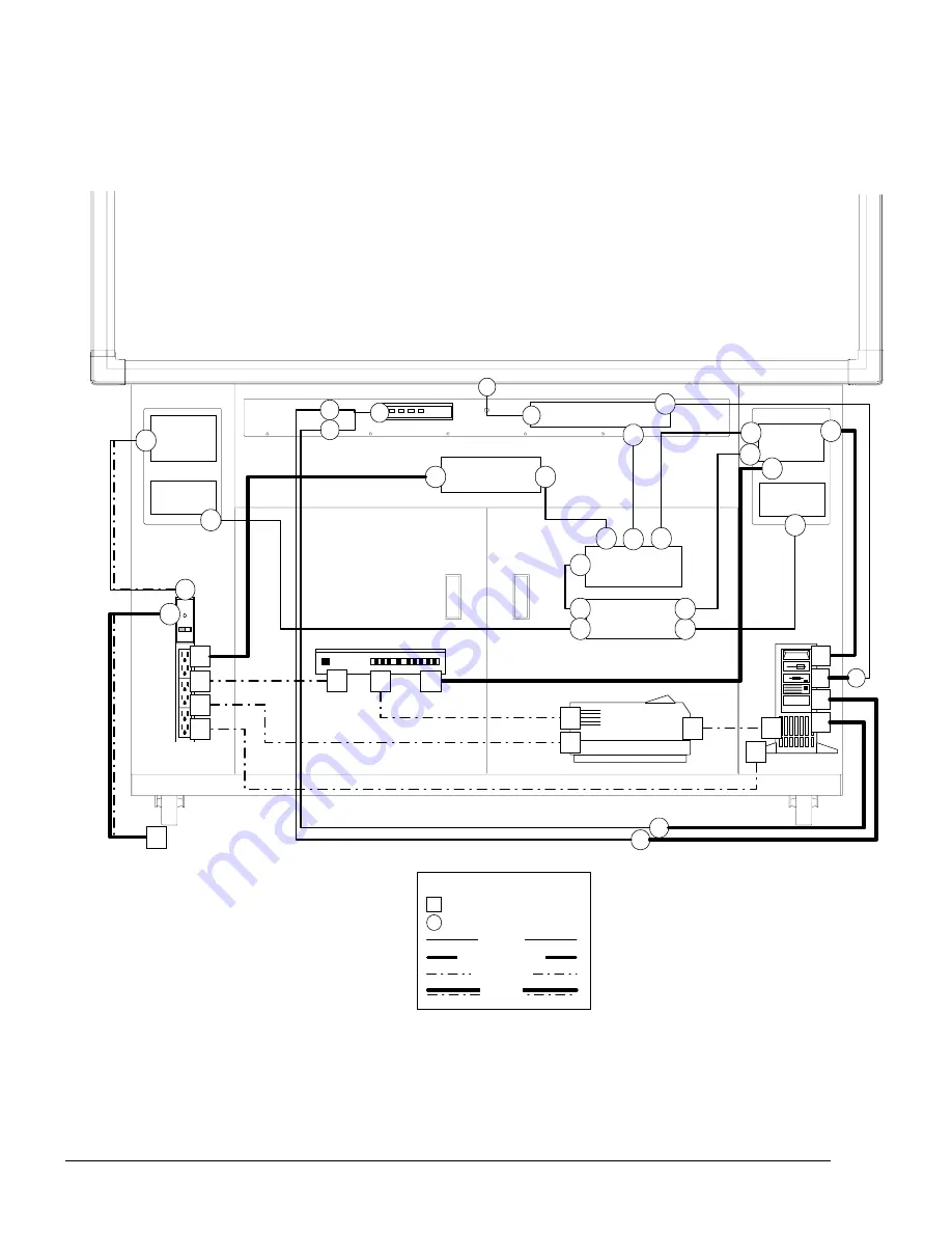
Integrated RPSB 1800 Wiring Diagram

Legend

Pre-wired

Not provided

# Customer installed connection
# Pre-wired connection

(where applicable)

Provided

Customer Installed

Internal PC

VCR

Right

Speaker

Left

Speaker

SMART Pen Tray

+12V Power

Distribution

+12V Power

Supply

Power

Panel

IR Receiver

1

26

24

60

80

82

90

52

5b

5a

4

5

7

6a

86

4

1

6b

54

66

48

62

62

50

64

64

(where applicable)

6a
6b

Projector

24

84

26

92

Power bar

(where applicable)

80
90

82

84
86

92

Amplifier

52

60

40

50

Audio

Mixer

66

40

54

48

Summary of Contents for Rear Projection SMART Board 1800

Page 1: ...1800 1802 E G F 1 C 5 4 B 3 2 1 A G D 10 10 9 8 7 6 3 2 F E ...

Page 2: ...ver is connected Consult the dealer or an experienced radio TV technician for help Any changes or modifications to this Class B digital device that have not been expressly approved by SMART Technologies Inc could void the user s authority to operate the equipment l l l l Trademark Notice Copyright Notice Rear Projection SMART Board SMART Board Universal Projector Assembly SMART X Port SMART Notebo...

Page 3: ... follow the overview describing the set up installation and wiring procedures for both cabinet models The first section The Rear Projection SMART Board 1800 1802 describes procedures common to both models that transform the cabinets from transport to operating position The second section Connecting Internal Wiring describes the procedures for wiring internal components Adjusting the Projected Imag...

Page 4: ...ptions in this manual apply to either system Any information that applies solely to Windows users is accompanied by a window icon in the margin Information relating only to Macintosh users is distinguished by a similarly placed apple icon NOTE Procedures common to both Windows and Macintosh are described in terms of Windows conventions ...

Page 5: ...nal 19 Remaining RPSB 1800 Power Connections 20 Connecting RPSB 1802 Components 21 Integrated RPSB 1802 Wiring Diagram 22 Table of RPSB 1802 Connections 23 RPSB 1802 Connection Procedures 25 RPSB 1802 Computer 1 Connections Windows 26 RPSB 1802 Projector Connections 28 RPSB 1802 VCR DVD Connections Optional 29 Remaining RPSB 1802 Power Connections 30 Switching on the Projector and Computer 31 RPSB...

Page 6: ...Contents ...

Page 7: ...lug the audio video and serial cables provided underneath the shelf into the laptop s appropriate ports An internal switch called the SMART X Port 10 automatically overrides the internal connections changing over the video audio and serial inputs from the internal computer computer 1 to the guest laptop computer 2 The data in the guest laptop is then displayed on the RPSB screen and if the SMART B...

Page 8: ...power source then complete the setup procedures described below NOTE Leave sufficient space around the entire cabinet so you can comfortably access it as you perform the following assembly and connection procedures Cabinet Tools Cables and Connectors Before you begin setting up the cabinet and its components take a minute to ensure you have the following tools at hand All tools except the Phillips...

Page 9: ...ror is rotated and secured inside the cabinet The rear mirror must be repositioned so that it extends beyond and is angled upward from the rear of the cabinet This accommodates the long projector throw distance required by the large size of the RPSB 1800 1802 SMART Board screen raises or lowers the door at the hinged side moves the door closer or further from the cabinet moves the doors closer or ...

Page 10: ...two mirror lock screws to lock the repositioned mirror in place in Step 4 The two lower baffle lock screws will be needed if your cabinet needs to be returned to transport position at a later date We recommend they be stored in the lip of the top baffle after completing Step 4 NOTE Do not remove the mirror pivot screws As their name implies these screws function as a pivot point for the mirror ass...

Page 11: ...see the words Pull Here so that the large rear mirror starts to rotate outwards NOTE Be very careful not to touch the mirror itself any fingerprints left on the mirror may obscure the projected image Mirror Pan Top Baffle Outer Baffle marked Pull Here Outer baffle Outer baffle Step 2 Lifting the Top Baffle Pulling on Outer Baffle ...

Page 12: ...nder the rotated rear mirror and then once you have gained access to the interior of the cabinet stand up in a somewhat crouched position to install the mirror lock screws While you re inside the cabinet ask someone to pass you the two lower baffle lock screws removed in Step 1 Put them in the lip of the lower baffle door If the cabinet needs to be returned to transport position in the future they...

Page 13: ...ntil it stops of its own accord TIP Ensure that side baffles of the lower baffle door are inside the cabinet If these baffles are positioned outside the cabinet the door will not lower all the way Lower baffle door Lower Baffle Door Step 5 Rotating the Lower Baffle Door ...

Page 14: ...ffle door handle and pull upwards and outwards to remove the lower baffle door from the standoff posts 3 Remove the four screws that secure the rear access panel to the cabinet 4 Pull the rear access panel away from the cabinet Installing the Projector NOTE Before you begin locate your projector on the RPSB 1800 1802 Projector Installation Reference List You should use the information contained in...

Page 15: ...jector is positioned properly on the platform The projector should be pointing at and perpendicular to the small mirror with the projector pointing at centered and perpendicular to the small mirror Then loosely secure the projector to the platform with the straps provided NOTE A centered image on the SMART Board can only be achieved if the projector is placed squarely on the platform Make sure the...

Page 16: ...bove Installing the Computer Place the computer inside the cabinet with the power button facing the front of the cabinet and secure with the two straps provided You can install the computer to the right or to the left of the projector While the computer straps are in place to the left of the projector it s a simple matter to unthread them from the cabinet floor slots and rethread them on the other...

Page 17: ...en Tray shelf directly in front of the infrared receiver already installed at the back of the Pen Tray shelf on the left side Pen Tray Optional Flip Up Shelf Included with 1802 Wireless Keyboard Volume Control Display Mode Switch 1802 only 2 The infrared receiver cable is secured in place inside the cabinet on the lower right side as you face the front of the cabinet See the wiring diagram on page...

Page 18: ...2 4 Refer to the wireless keyboard manual for instructions to complete the set up If you have an RPSB 1800 turn to page 13 for component connection procedures If you have an RPSB 1802 turn to page 21 for component connections procedures ...

Page 19: ...ection partially pre wired connections or you ll be asked to connect both ends of a cable that comes with an installed component no pre wiring In the wiring diagrams that follow bold lines represent supplied cables that are partially pre wired and broken lines represent unprovided component cables that require connection at both ends Square nodes represent customer installed connection sites NOTE ...

Page 20: ...licable Provided Customer Installed Internal PC VCR Right Speaker Left Speaker SMART Pen Tray 12V Power Distribution 12V Power Supply Power Panel IR Receiver 1 26 24 60 80 82 90 52 5b 5a 4 5 7 6a 86 4 1 6b 54 66 48 62 62 50 64 64 where applicable 6a 6b Projector 24 84 26 92 Power bar where applicable 80 90 82 84 86 92 Amplifier 52 60 40 50 Audio Mixer 66 40 54 48 ...

Page 21: ...aker wire Power amplifier to left speaker 52 Fully Right speaker wire Power amplifier to right speaker 54 Partially 3 5mm audio cable Audio mixer to computer DC Power Connections 60 Fully DC to DC power cord DC power distribution to power amplifier 62 Fully DC cord attached to switching power supply DC power distribution to switching power supply 64 Fully DC to DC power cord DC power distribution ...

Page 22: ...w remaining power connections These connections are described in detail in the sections that follow In the wiring diagrams that accompany each set of procedures bold lines represent cables that require connections that you must make RPSB 1800 Computer Connections Windows Internal PC VCR Right Speaker Left Speaker SMART Pen Tray 12V Power Distribution 12V Power Supply Power Panel IR Receiver 1 26 2...

Page 23: ...rt adaptor 3 If your computer s COM port has 25 pins replace the DB9 port adaptor 7 above with 25 pin port adaptor 18 in table 4 For a Windows computer insert the serial port adaptor into a vacant COM port For a Macintosh computer insert the barrel shaped Mini DIN8 17 connector end of the MOD6 cable into the printer or modem port 5 Connect the 3 5mm audio cable 54 originating at the audio mixer to...

Page 24: ...he power bar 1 Attach the HD15 video cable that comes with your projector into the video input port on the projector 2 Connect the other end of the HD15 video cable to the video output monitor port on the computer NOTE Refer to your projector s manual for more detailed directions 3 Connect the projector s power cable into the power bar NOTE Cabinets shipped in North America and Japan are supplied ...

Page 25: ...ct the RCA composition video cable s yellow RCA video connector into the video out port of the VCR This port may be labeled To Monitor 2 Plug the other end of this connector into the composite connector on the back of the projector 3 Connect the RCA audio cable 48 originating at the audio mixer to the VCR audio jacks 4 Connect the VCR s power cable to the power bar NOTE Cabinets shipped in North A...

Page 26: ...80 90 82 84 86 92 Amplifier 52 60 40 50 Audio Mixer 66 40 54 48 Final RPSB 1800 Power Connections To make final power connections 1 Outside North America and Japan connect the power cord 80 originating at the switching power supply to the power bar 2 In North America and Japan plug the power bar cable 92 originating at the power bar into a wall socket NOTE Outside North America and Japan plug the ...

Page 27: ...f a cable that comes with an installed component no pre wiring In the wiring diagrams that follow bold lines represent supplied cables that are partially pre wired and broken lines represent unprovided component cables that require connection at both ends Square nodes represent customer installed connection sites NOTE For cables that are fully pre wired the numbers in the figure below are for info...

Page 28: ...able Computer 2 Computer 1 VCR Right Speaker Left Speaker SMART Pen Tray 12V Power Distribution 12V Power Supply Power Panel IR Receiver 26 80 82 90 52 5a 4 5 6a 86 6b 48 62 62 50 where applicable 6a 6b Projector 84 26 92 80 90 82 84 86 92 Amplifier 52 40 50 2 SMART X Port 10 42 44 46 46 8 14 2 12 12 22 22 20 20 10 10 28 44 68 68 28 64 4 5b 60 60 Audio Mixer 66 14 40 48 42 64 66 Legend Pre wired N...

Page 29: ...ort 10 to internal and guest Macintosh computer 20 Partially HD DB15M to HD DB15M X Port 10 to computer 1 22 Partially HD DB15M to HD DB15M X Port 10 to computer 2 26 No User provides installs RCA video cable that comes with VCR Projector to VCR 28 No User provides installs HD15 video cable that comes with projector Projector to X Port 10 Audio Connections 40 Fully 3 5mm audio cable Audio mixer to...

Page 30: ... power panel North America and Japan only 84 No User provides installs Power cord that comes with the projector Power bar to projector 86 No User provides installs Power cord that comes with the computer Power bar to computer 1 90 No User provides installs Power cord that comes with the VCR Power bar to VCR 92 Partially with supplied power bar only Power bar cord to wall power outlet Power bar to ...

Page 31: ...jector connections from the projector to the SMART X Port 10 and power bar VCR DVD connections from the VCR DVD if installed to the projector audio mixer and power bar a few remaining power connections guest laptop computer 2 connections from the laptop to the X Port 10 These connections are described in detail in the sections that follow In the wiring diagrams that accompany each set of procedure...

Page 32: ...ART Pen Tray 12V Power Distribution 12V Power Supply Power Panel IR Receiver 26 80 82 90 52 5a 4 5 6a 86 6b 48 62 62 50 where applicable 6a 6b Projector 84 26 92 80 90 82 84 86 92 Amplifier 52 40 50 2 SMART X Port 10 42 44 46 46 8 14 2 12 12 22 22 20 20 10 10 28 44 68 68 28 64 4 5b 60 60 Audio Mixer 66 14 40 48 42 64 66 RPSB 1802 Computer 1 Connections Windows ...

Page 33: ...ini DIN8 connector Macintosh Serial Adaptor 2 Connect the 3 5mm audio cable 44 originating at the X Port 10 to the Audio Line Out jack on the back of the computer 3 Connect the HD DB15 video cable 20 originating at the X Port 10 to the video port on the computer For a Macintosh computer connect the Macintosh Video Adaptor 15 located in the Accessory Kit to the video port Connect the DB15 connector...

Page 34: ...4 26 92 80 90 82 84 86 92 Amplifier 52 40 50 2 SMART X Port 10 42 44 46 46 8 14 2 12 12 22 22 20 20 10 10 28 44 68 68 28 64 4 5b 60 60 Audio Mixer 66 14 40 48 42 64 66 RPSB 1802 Projector Connections To connect the projector to the X Port 10 and power bar 1 Using the HD15 Video cable that comes with your projector plug one end into the projector port on the projector and the other end into the pro...

Page 35: ... 10 42 44 46 46 8 14 2 12 12 22 22 20 20 10 10 28 44 68 68 28 64 4 5b 60 60 Audio Mixer 66 14 40 48 42 64 66 RPSB 1802 VCR DVD Connections To connect the VCR to the projector the audio mixer and the power bar 1 Connect the yellow RCA video connector to the video out port of the VCR This port may be labeled To Monitor Plug the other end of this connector into the composite connector on the back of ...

Page 36: ... 12 12 22 22 20 20 10 10 28 44 68 68 28 64 4 5b 60 60 Audio Mixer 66 14 40 48 42 64 66 Final RPSB 1802 Connections 1 Outside North America and Japan connect the power cord 80 originating at the power supply to the power bar 2 In North America and Japan ensure that the on off switch at the front of the cabinet see cabinet figure on opposite page is in the off position 3 In North America and Japan p...

Page 37: ...n the projector and computer Some peripherals will need to be separately switched on each time you power up the RPSB system 2 Determine if the projector must be switched to rear projection reversed image mode or if it can remain in front projection mode by looking at the image If the image is reversed when you look at it from the front switch the projector to rear projection mode 3 If your project...

Page 38: ... 46 46 8 14 2 12 12 22 22 20 20 10 10 28 44 68 68 28 64 4 5b 60 60 Audio Mixer 66 14 40 48 42 64 66 RPSB 1802 Computer 2 Connections 1 Pull the cable assembly out from inside the recess located under the side mounted flip up shelf 2 Connect serial cable 12 video cable 22 and audio cable 46 all three originating at the X Port 10 to the appropriate ports on computer 2 For a Macintosh guest laptop co...

Page 39: ...your owner s manual 3 If computer 2 is not on turn it on The boot up screen will appear on the RPSB screen If no image appears on the RPSB screen Activate the external video port on computer 2 Some laptop computers can t display their internal screens and activate the external video port or external monitor at the same time Check your laptop computer manual for the command that activates the exter...

Page 40: ...hout disconnecting computer 2 The LEDs on either side of the switch indicate which computer is active at the current time Volume Control Display Source Switch 1802 only Location of Display Source Switch Internal External Volume Knob Display Source Switch Computer 1 LED Indicator Computer 2 LED Indicator Close up of Volume Knob and Display Source Switch ...

Page 41: ...an the optimal one are permitted you should not set the resolution to any of these other settings For example if the projector s true resolution is 800 x 600 but it s also capable of displaying at 640 x 480 set both the computer and the projector to the true resolution 800 x 600 IMPORTANT If the resolution of the projector is set to anything other than the true resolution or if the computer and pr...

Page 42: ...o to the Select a monitor setting box and select the resolution setting that matches the resolution of your projector 6 Click OK 2 Adjusting the Small Mirror While making adjustments check both the reflection in the small mirror and the actual image on the screen For an optimal image the reflection must be in the center of the small mirror and each side must be symmetrical The projector should be ...

Page 43: ...s so they do not block the projector light path If you see cable shadows on the screen when the projector is turned on make further adjustments to the cable positions 3 Adjusting the Projector You must make a few final adjustments to the projector to ensure a focused image that fits within the bezel of your SMART Board at the top and bottom with a margin of approximately 3 8 on both right and left...

Page 44: ...e is keystoned along the sides that is the side margins are different widths see the figure on the next page you may need to raise or lower the front or back of the projector slightly If the image is keystoned along the top or bottom the sides of the image are not of equal length the projector is not positioned properly at a right angle to the small front mirror You may need to move only the back ...

Page 45: ...r access panel and lower baffle door to the cabinet 2 Tighten the screws Installing the SMART Board Software Every RPSB comes with two pieces of software the SMART Board driver and SMART Notebook These two programs are combined in a single executable called SMART Board Software The SMART Board driver activates your RPSB allowing you to use your finger as a mouse annotate over an application with e...

Page 46: ...u want to install 8 Follow the on screen installation instructions to select a destination folder for the SMART Board Software Configuring and Orienting the SMART Board After installing the SMART Board Software you must perform two procedures configuring and orienting the SMART Board Configuring the SMART Board involves specifying which COM port your computer uses and whether or not you are using ...

Page 47: ... Board from the Board menu either from the SMART Board driver window or right mouse click on the SMART Board System Tray icon or Press the Orient SMART Board button on the initial Board driver window or Click or press twice on the SMART Board icon in the System Tray or Press the two Pen Tray buttons simultaneously holding for at least one second The Pick the Orientation Precision dialog box will a...

Page 48: ... You will hear a beep and the next cross in the series will be highlighted in red NOTE If you press on the crosses out of sequence or inaccurately a Bad Orientation Point dialog box will appear To correct the bad orientation select the OK button at the bottom of the screen using the mouse attached to your computer This is necessary because the system has lost Board awareness while orienting When y...

Page 49: ... T2R 1K9 Warranty Rear Projection SMART Boards manufactured by SMART Technologies include a one year parts and labor warranty Customers must return any defective merchandise to an authorized service center as directed by the reseller or manufacturer Warranty Shipping Charges Shipping charges incurred from warranty service are paid as follows The customer is responsible for shipping the system to t...

Page 50: ...n the SMART Board surface and immediately wipe with a paper towel or soft cloth If a permanent marker has been used try rubbing the spot with a cloth dampened with isopropyl alcohol Then use a standard glass cleaner to thoroughly clean the surface Preventing Damage to the Writing Surface While the SMART Board is very durable sharp objects can scratch or cut the surface Sharp writing instruments su...

Page 51: ... baffle slightly Close the top baffle then install the mirror lock screws and the lower baffle lock screws removed during the original cabinet installation Ensure the lower door is secured in place Lower Baffle Door Top Baffle Mirror Remove mirror lock screws and rotate mirror upwards Top Baffle Mirror Lock screws Lower baffle lock screws ...

Page 52: ...t through a narrow or low doorway 1 Locate the four cap screws and lock washers at the rear of the screen in each corner 2 Remove the cap screws with the 3 16 ball screwdriver provided with the cabinet Do not remove the stud below the cap screw Stud Lock Washer Cap Screw Key Hole Stud rests here MOD4 Cable Cap Screw 4 Places SMART Board Corner Cap Screws Removing the Cap Screws ...

Page 53: ...ol varsol water or acetone to clean this surface These substances will render your SMART Board unusable 5 Remove the screen mounting bracket at the top to the cabinet as shown in the figure below The three mounting screws are fastened from inside the cabinet Use the 1 8 Allen key provided with the cabinet 6 To reconnect the SMART Board to the cabinet re attach the top screen mounting bracket loose...

Page 54: ...d other devices plugged into the power bar will start up and the computer s desktop will appear on the SMART Board screen Touch the SMART Board If a cursor appears and it tracks the movements of your finger go to the topic Navigating Around the SMART Board on the next page If the cursor fails to track your finger movements continue from step 2 below If the cursor fails to track your finger movemen...

Page 55: ...ck on the SMART Board press twice with your finger Avoid lifting your finger from the surface of the Board between the first and second press of a double press This ensures that the two contact points are very close to each other registering as a double click rather than as two discrete contact events Starting up SMART Notebook Use your finger to double click on the SMART Notebook icon on your scr...

Page 56: ...andby mode This allows the lamp to cool before final shut down Your projector manual may recommend that you wait a couple of minutes for the projector s fans to cool the lamp 4 Turn the on off switch at the front of the cabinet to off This will shut down the computer the projector and any other devices connected to the power bar ...

Page 57: ...the three Shelf Mounting Screws removed in Step 1 3 If your camera has a standard 1 4 20 camera mount use the 1 4 20 Screw provided to mount the camera through one of the series of holes on top of the Camera Shelf Use the 3 16 ball driver which came with the cabinet Depending on the height of the camera s feet you may need to use some of the Washers provided to adjust the height of the screw 4 Con...

Page 58: ...s caused by projecting onto a surface at an angle Mini RJ11 connector The connector end of a MOD4 cable A close look at a mini RJ11 connector will reveal four tiny contacts set into four slots It may also be known as a telephone handset connector or RJ22 MOD4 cable A flat modular cable consisting of 4 wires covered in a protective sheath It connects the SMART Board to the Pen Tray in an RPSB unit ...

Page 59: ...o extend the unique presentation capabilities of the RPSB to many other popular conferencing applications SMART Board driver The software that drives or activates a SMART Board The software allows you to use your finger as a mouse annotate over an application with electronic ink and use SMART Notebook and other Board aware applications Throw distance The distance a projector must be set from the p...

Page 60: ...Contents 1 P Pen Tray shelf 1 Pick the Orientation Precision dialog box 37 Projector adjustment 31 bolting to platform 7 installation 6 lens placement 33 recommended brightness 1 resolution 29 start up 44 strapping in place 6 switching on 25 throw distance 34 Pulling out the Pen Tray shelf 7 Q Quick orientation 37 Quick Setup Guide 1 R Ready light 44 Rear mirror repositioning 3 Rear Projection SMA...

Page 61: ...eeting Pro 1 SMART Notebook 1 35 45 start up 45 SMART X Port 10 1 Software Installation Macintosh 36 Windows 95 36 Standard orientation 37 Strapping the projector 6 Supplied Software 1 Switching on the Projector and Computer 25 T Table of Cabinet Connections RPSB 1800 11 RPSB 1802 18 Throw Distance 33 Transporting the RPSB 40 U User Registration Card 39 Using the RPSB 44 V Variables in Projector D...

Page 62: ...ologies Inc Suite 600 1177 11th Avenue SW Calgary AB CANADA T2R 1K9 Support 1 888 42 SMART Tel 403 228 5940 Fax 403 245 0366 E mail support smarttech com www smarttech com Printed in Canada RC8 MAN 00 REV B ...

Reviews: