


1. Optional: handles, escutcheons, fittings and other door furniture fitted
to the door are to be removed.
2. SmartHandle is partly assembled when supplied; see "Disassembly".
3. Optional: In a lock with an 8.5 mm or 10 mm spindle, push the corres-
ponding sleeve (8 mm --> 8.5 mm [not included in the supply package]
or 8 mm --> 10 mm) through the retainer opening in the mortise lock
from the inside.
4. Push the inside fitting (8) spindle through the retainer slot in the door's
mortise lock (6), so that the fitting is flush with the door. Ensure that
you do not squash the 2-pole cable when doing so.
5. Position the inside fitting (8) in such a way that it is parallel to the door.
6. Mark the drill holes required on the door through the corresponding
holes in the inside fitting (8).
7. Remove inside fitting (8) from the door.
8. Drill the holes with a diameter of 8 mm (top hole) and 13 mm (lower
hole) through the door.
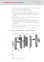
9. Push inlay (1) onto the outer handle (3). Depending on the handle
model, it may not be possible to fit it once the handle is installed.
10. Insert outer handle (3) horizontally into the outer fitting (4) until it will
go no further, placing it in the direction that you require, depending on
whether it is a DIN left-hand or right-hand door.
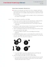
11. Place handle fastener piece (5) into position (see Figures 2 and 3).
12. Hold the outside handle (3) and use the spanner to rotate the fastener
piece (5) about 75° to the right until it fits into position (Figures 4 and
5). If you do not fit it correctly, the handle may come loose again.
13. The inside fitting (8) is mounted onto the inner surface of the door. Push
the spindle for the inside fitting (8) through the retainer slot in the mor-
tise lock (6) and push the inside fitting onto the door until it is about 5
cm away.
14. The outer fitting (4) is mounted from the outer side of the door.
15. Insert the lower spacing bolt (7) into the outer fitting (4); the upper spa-
cing bolt (7) is pre-fastened into position in the factory.
16. Push the cable from the outer fitting through the lower hole (13 mm in
diameter) and through the opening in the cable escutcheon. Ensure you
do not catch or buckle the cable while doing so.
17. Push the retainer slot in the outer fitting (8) onto the spindle and push
the two spacing bolts (7) through the drill holes in the door while pulling
the outer fitting cable inwards in such a way that it is always taut. In do-
ing so, ensure that the outer fitting cable does not get caught or
buckled.
SmartHandle
SmartIntego
(Manual)
8. Installation (manual)
94 / 160
Summary of Contents for SI:SmartHandle Series
Page 1: ...SmartHandle SmartIntego Manual 28 10 2020...
Page 25: ...6 5 Distances and door thicknesses SmartHandle SmartIntego Manual 6 Designs 25 160...
Page 131: ...SmartHandle SmartIntego Manual 8 Installation manual 131 160...
Page 132: ...9 Outer fitting is mounted SmartHandle SmartIntego Manual 8 Installation manual 132 160...
Page 136: ...2 Remove the uppermost battery SmartHandle SmartIntego Manual 8 Installation manual 136 160...
Page 137: ...3 Screw on the inside fitting SmartHandle SmartIntego Manual 8 Installation manual 137 160...
Page 145: ...10 Configuration See TechGuide WO SVCN SmartHandle SmartIntego Manual 10 Configuration 145 160...
Page 147: ...12 Signal See TechGuide WO SVCN SmartHandle SmartIntego Manual 12 Signal 147 160...