


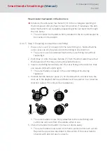


12. Place handle fastener piece (5) into position (see Figures 2 and 3).
13. Hold the outside handle (3) and use the spanner to rotate the handle
fastener piece (5) about 75° to the right until it fits into position (Figures
4 and 5). If you do not fit it correctly, the handle may come loose again.
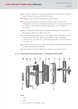
14. The inside fitting (8) is mounted onto the inner surface of the door. Push
the inside fitting spindle through the retainer slot in the mortise lock and
push the inside fitting onto the door until it is about 5 cm away.
15. Push the 3-pole cable for the inside fitting through the lower hole (13
mm in diameter) and ensure that it doesn't get caught or buckled.
16. Push inside fitting (8) through the door completely, so that it is flush
with the door. In doing so, place the cable escutcheon into the lower drill
hole.
17. The outer fitting (4) is mounted from the outer side of the door.
18. Insert the lower spacing bolt (7) into the outer fitting (4); the upper spa-
cing bolt (7) is pre-fastened into position in the factory.
19. Push the outer fitting retainer slot onto the spindle while pushing the
two spacing bolts (7) through the drill holes up to a gap of 2 cm.
20.Insert the 3-pole cable through the cut-out in the lower end of the outer
fitting.
21. Push the outer fitting (4) onto the door completely. In doing so, ensure
that the inside fitting cable does not get caught or buckled.
22. Connect the 3-pole cable from the inside fitting to the 3-pole cable
from the outer fitting. This cable can only be inserted in one direction.
Do not pull on the cables while doing so; just carefully secure the plug-in
connection into position.
23. The 2-pole cable from the outer fitting can hang freely, but must not get
caught when the outer cover (2) is fitted. Do not pull on the cable.
24.Press outer and inside fittings together, so that they are both flush
against the door.
25. Press the electronics module cover lid in the inside fitting (8) carefully
out of its bracket and fold back horizontally. Make sure that the elec-
tronics are not exposed to mechanical load and are not damaged in any
other way.
26.Carefully remove the upper battery (10) from the holder. Use clean
gloves free of fat or grease to handle batteries.
27. Insert the supplied screws (9) through drill holes in the inside fitting (8)
from inside the door and fasten to the spacing bolts (7) on the outer fit-
ting by hand, using about 5-7 Nm.
SmartHandle
SmartIntego
(Manual)
8. Installation (manual)
92 / 160
Summary of Contents for SI:SmartHandle Series
Page 1: ...SmartHandle SmartIntego Manual 28 10 2020...
Page 25: ...6 5 Distances and door thicknesses SmartHandle SmartIntego Manual 6 Designs 25 160...
Page 131: ...SmartHandle SmartIntego Manual 8 Installation manual 131 160...
Page 132: ...9 Outer fitting is mounted SmartHandle SmartIntego Manual 8 Installation manual 132 160...
Page 136: ...2 Remove the uppermost battery SmartHandle SmartIntego Manual 8 Installation manual 136 160...
Page 137: ...3 Screw on the inside fitting SmartHandle SmartIntego Manual 8 Installation manual 137 160...
Page 145: ...10 Configuration See TechGuide WO SVCN SmartHandle SmartIntego Manual 10 Configuration 145 160...
Page 147: ...12 Signal See TechGuide WO SVCN SmartHandle SmartIntego Manual 12 Signal 147 160...