Sifos Technologies PowerSync PSA100 Technical Reference Manual Download Page 46

PowerSync Analyzer Reference Manual 

March 9, 2010 

                                   Sifos Technologies page 


46

 
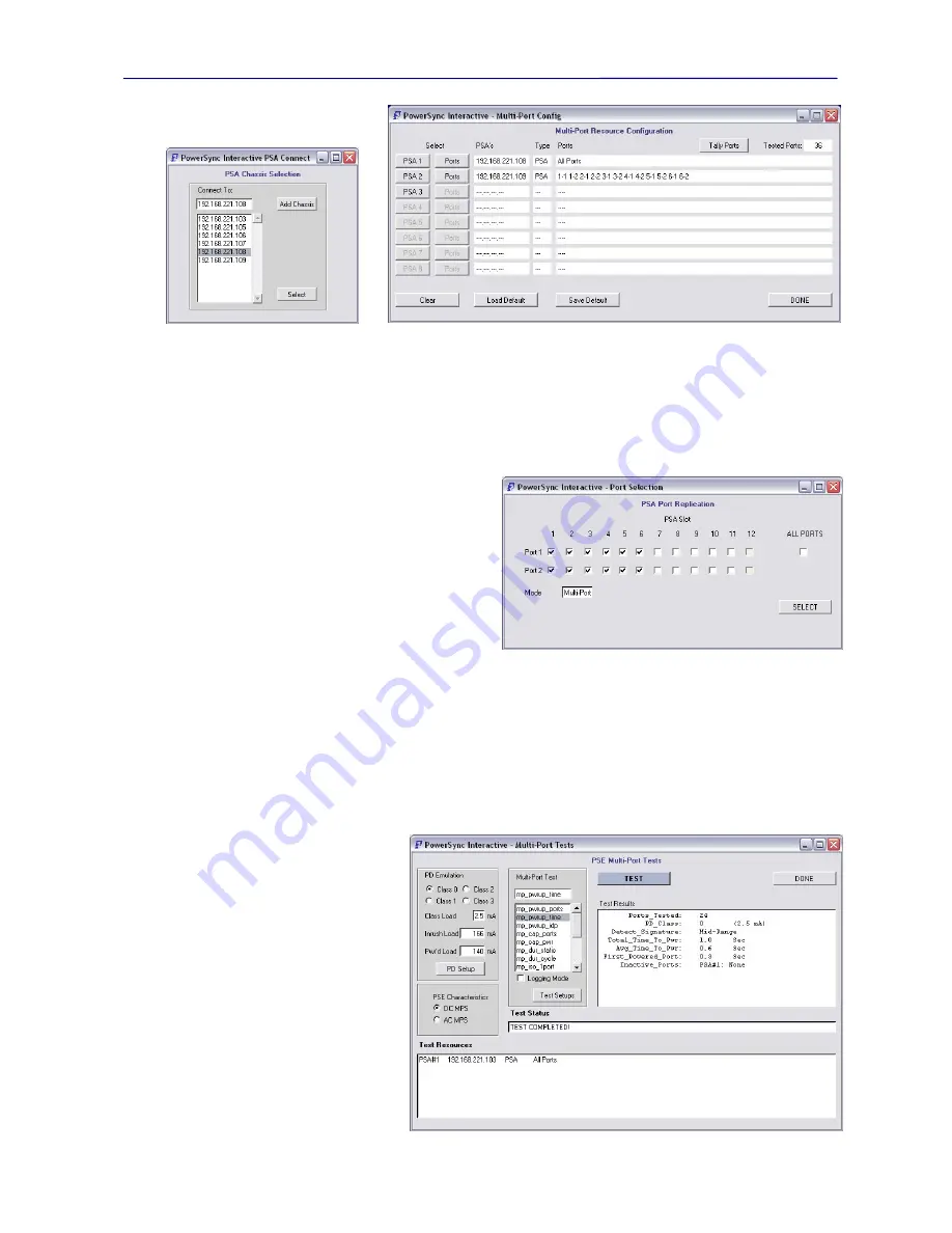
To add a PSA to the test resource field, each 

PSA N

 button opens a menu 

(Figure 3.35)

 identical to the 

Chassis 

Selection

 menu seen in Section 3.1.3.   PSA Addresses may be entered, selected from the current list of known PSA’s, 

or added to the list of known PSA’s.  Many of the same rules apply here as would apply with the 

Chassis Selection


menu.   PSA addresses that are entered or selected MUST be available on the local network, or otherwise they will be 
rejected.   Additionally, each PSA added to the 

PSA’s

 column must be unique – there can be no duplication of 

addresses from row to row.    If a repeat PSA address is entered, it will not be added to the test resource field.  
   
Once a valid PSA address has been assigned to the 
Multi-Port test resource field, an associated 

Ports

 button 

activates to enable the assignment of test ports from that 
PSA chassis.   The 

Ports

 sub-menu 

(Figure 3.37)

 is very 

similar to the Copy Settings menu seen earlier.  The 
required test ports may be individually selected or, in the 
event where all PSA test ports are utilized, the 

ALL 

PORTS

 option may be selected.  This menu will only be 

enabled for the available test ports within the associated 
PSA chassis.   If fewer than 24 test ports (12 test blades) 
are installed, then ALL PORTS will only include those 
test ports that exist within the associated PSA chassis. 
 
At any time, as resources are configured, the 

Tally Ports

 button may be used to summarize all test port resources 

currently assigned for Multi-Port testing.   The 

Save Default

 button will store a non-volatile Multi-Port Resources 

configuration according to whatever is currently configured in the menu.  The 

Load Default

 will load a previously 

saved Multi-Port Resource configuration into the menu.    When resource configuration is completed, the 

DONE

 button 

will actually perform full resource availability checking as the menu is closed. 

3.3.2. 

Multi-Port PSE Test Menu 

Following the same model as is used with PSE Conformance Testing, Multi-Port Tests may be run individually or 
automatically sequenced to a standard report facility.   The 

Multi-Port PSE Test

 menu 

(Figure 3.38)

 enables the 

execution of individual Multi-Port tests 
within the previously defined Multi-
Port Test Resource field. 
 
At the bottom of the 

PSE Multi-Port 

Tests

 menu are the test resources that 

are defined using the 

PSE Multi-Port 

Configure Resources

 menu.   These 

resources must be present in order to 
run Multi-Port tests. 
 
Within the 

PSE Multi-Port Tests

 menu 

are 3 sub-menus for specifying tests and 
test conditions.   The 

PD Emulation


sub-menu allows the selection and 
configuration of PD Emulation 
characteristics that will be applied to all 
test ports as Multi-Port tests are run.   
PD’s may be selected as 

Class 0

,  

Figure 3.37

Multi-Port Port Select Dialog


Figure 3.38

Multi-Port Selected Test Menu

Figure 3.35


Multi-Port Chassis Select


Figure 3.36

Multi-Port Test Field Configuration Menu


Summary of Contents for PowerSync PSA100

Page 1: ...er Reference Manual March 9 2010 Sifos Technologies page i Sifos Technologies PowerSync Analyzer PSA100 PSA1200 PSA2400 Technical Reference Manual Version 3 4 Revised March 9 2010 Copyright 2006 2010 Sifos Technologies ...

Page 2: ... the user documentation Except as permitted by such License Agreement no part of this publication may be reproduced stored in a retrieval system or transmitted in any form or by any means without the prior written permission of Sifos Technologies Inc Information contained in the user documentation is subject to change without notice and does not represent a commitment on the part of Sifos Technolo...

Page 3: ...ata OUT Ports 16 2 4 System Software Overview 17 2 4 1 PSA Interactive 17 2 4 2 PowerShell Scripting Environment 17 2 4 3 PSE Automated Test Suites 18 2 4 4 PowerSync Analyzer Configuration Files 18 2 4 5 Directory and File Organization Microsoft Windows 20 2 4 6 Directory and File Organization Linux and Unix 20 2 4 7 TK TCL Requirements Resources 21 2 5 Network Connection and Host Firewall Consid...

Page 4: ... ALT A MDI PSE on Port 1 1 54 3 5 Enabling PSA Interactive for the PSA2400 55 4 PowerShell Scripting Environment 57 4 1 TCL and Wish Shells 57 4 1 1 Tcl Versus Wish in the PC Windows Environment 57 4 2 PSA Connection Dialog 57 4 3 PowerShell Syntax Conventions 58 4 4 PowerShell Help Capabilities 58 4 5 PowerShell Connection and Configuration Commands 59 4 6 Test Port Configuration Commands 60 4 7 ...

Page 5: ...ware Requirements 111 7 2 PSE Conformance Testing High Power PSE s 112 7 3 PSE Conformance Test Reporting 112 7 4 PSA Interactive Conformance Test Menus 114 7 5 Sequencing PSE Conformance Tests from PowerShell 114 7 6 PSA Interactive and High Power Testing 115 7 7 PowerShell Extensions for High Power PSE Testing 117 8 Specialized Scripting with the PSA1200 121 8 1 Optimizing Test Speed for High Vo...

Page 6: ...s page vi 9 2 PoE Service Test Reporting 142 9 3 PoE Intermittent Service Detection 143 9 4 Visual PoE Analysis 144 9 5 PoE Service Test Configurations 145 9 6 PSA Interactive and the PoE Service Analyzer 146 9 7 Accessing the PoE Service Analyzer from PowerShell 147 ...

Page 7: ... be controlled from a PC over a TCP IP network connection 10 100BaseT Multiple PowerSync Analyzer instruments of varying configuration may be controlled from a single controller Each test port works in conjunction with host software to provide various Powered Device PD load emulation functions along with an assortment of PSE measurement and analysis functions 1 2 Reference Manual Organization Sect...

Page 8: ...t tests are fully automated and will automatically produce comprehensive reports that clearly identify trouble spots or performance anomalies Multi Port testing is complemented by virtually unlimited user control over characteristics of emulated Powered Devices PD s during the course of testing The PSE Multi Port Test Suite is purchased as an option or an upgrade for each PSA instrument Section 7 ...

Page 9: ...onal LLDP MAC Layer based protocol for negotiating power demands with a PD with granularity of 0 1 watts PoE End Point and Mid Span PSE s with full gigabit Ethernet support 2 1 1 The Power Connection Under the 802 3af specification DC power must be carried on 2 of the 4 pairs of a LAN e g category 5 cable Either 48V or 48V DC is carried on one pair common mode and reference zero volts is carried o...

Page 10: ...esistance 15 19 KΩ Maximum Acceptable Load Capacitance 0 15 10 μF Slew Rate of Voltage Step 0 1 V μsec Detection Duration 500 mSec Detection Backoff following unsuccessful detection does not apply to End Point PSE s 2 Sec It should be noted that despite the various requirements described for PD Detection signaling in the 802 3 specification that there is considerable room for design variation and ...

Page 11: ...g criteria of interest Time from end of detection until power up is complete and the rise time of the PoE voltage The first parameter includes classification time and must be under 400 mSec The power on rise time is required to be longer than 15 μsec Other parameters of interest during the power on event are the initial in rush current and the peak to peak ripple and noise amplitude PSE s are requ...

Page 12: ...es allowance for the DC MPS signature to be intermittent so long as it is present for a continous 60 msec out of every 360 msec interval The main advantage of DC MPS is that it does not add any noise onto the power rail 2 2 Power Sourcing Equipment Characteristics The 802 3af specification leaves considerable room for implementation dependent behaviors Additionally many vendors of Power Sourcing E...

Page 13: ...s utilized proprietary technology to generate and manage power over LAN Typical legacy powered devices include a low frequency coupling circuit between data transmission pairs and or the existence of a large capacitance seen by common mode measurements across either data or spare pairs These features could be sensed by the power sourcing equipment using proprietary techniques Protocols for determi...

Page 14: ...and within all PowerSync Analyzers excluding the PSA PL may be used as a triggering event for many single shot measurements of detection and MPS behaviors The Detection Passives are affected by an internal disconnect feature that is dependent only upon the PSE voltage level When the PSE voltage reaches approximately 11 volts the passive R C Detection signature is removed and the MPS signature R C ...

Page 15: ...surements or actions and is initiated by either a user command an action that is programmed to send out an external trigger or through an external event that appears on the trigger bus The trigger bus is a trigger signal connection that is shared by all ports within a system and by the Trig Out BNC connector on each PowerSync Analyzer Figure 2 8 shows the sources used to generate External or event...

Page 16: ...mmand The AC Meter is capable of measuring ripple in either a 16 Hz 5K Hz band or in a 5K 300K Hz band 3dB BW This measurement is a peak to peak voltage measurement based upon a sample rate of approximately 20K samples per second Since this is a peak to peak measurement of ripple on a steady state voltage there are no triggers associated with this measurement Integration period can be programmed f...

Page 17: ...ructed on top of the PowerShell API It offers robust control of most PowerSync Analyzer functions It is intended for users who intermittently or regularly use the PowerSync Analyzer for PD emulation and PSE measurements as well as for PSE Conformance PSA 1200 and PSE Multi Port PSA 1200 and PSA PL testing 2 4 2 PowerShell Scripting Environment PowerShell provides command level access to the PowerS...

Page 18: ... cycles of testing 2 4 4 PowerSync Analyzer Configuration Files PowerSync Analyzer software utilizes two local configuration files that can be adapted for a number of characteristics that are local to a user s setup and testing requirements These files are located as follows Operating System Config Directory Location Windows NT Windows XP Program Files Sifos PSA1200 Config Windows Vista Windows 7 ...

Page 19: ... Specifies whether PSE utilizes AC or DC MPS method to remove power from a PD This setting will be affected by the DC MPS vs AC MPS PSE Description controls in the PSA Interactive PSE Conformance Test menus and Multi Port Test Menus see Section 3 3 Default_ALT_Setting Specifies how to initialize all ports within the PowerSync Programmable Load for ALT pair selection Initialization is performed ONL...

Page 20: ...PC files will be populated to particular directories as described in the following table Directory Path Directory Files PowerShell Script Library PowerShell Wish and PowerShell Tcl Executables PSA Initialization Script PowerShell Wish and PowerShell Tcl resource files documentation Various PSA reference documents C Program Files Sifos PSA1200 PSA Interactive PSA Interactive Script Library and vari...

Page 21: ...aller and Removal Scripts Version information concerning individual PowerSync Analyzer software libraries is available from PSA Interactive PL under the Help menu as well as from PowerShell using the psa_version command 2 4 7 TK TCL Requirements Resources PowerSync Analyzer software was developed utilizing Tcl Tk version 8 4 5 Generally there should not be a problem with using newer versions of Tc...

Page 22: ...der for the instrument to operate properly under control of PowerSync Analyzer software 1 There must be two or more chassis making up a PSA2400 available and operating on the same subnet in order for interaction with one chassis to be successful 2 Each of the two or more PSA2400 chassis must each contain 12 dual PSE test blades for a total test port capacity of 24 ports per chassis 3 PowerSync Ana...

Page 23: ...1sec Resolution 100µs 2 7 2 Measurements DC Voltage Pair to Pair Type Peak Average or Trace Range 0 to 60V Resolution 64 mV Error 1 2 13 mV Peak Types Max or Min Trace Length 256 Samples Triggers Immediate Internal External DC Current Powered Pair Type Peak Average or Trace Range 0 to 511 mA Resolution 0 5 mA Error 1 2 25mA Peak Types Max or Min Trace Length 256 Samples Triggers Immediate Internal...

Page 24: ...trol Interface Ethernet 10 100BaseT Host Requirements PC or Lap Top Windows NT 98 2000 or XP Control Environment Sifos PowerShell or PSA Interactive Network Latency 5 msec 2 7 5 Physical and Environmental Width 19 Height 5 25 3 Rack Unit Depth 12 Weight 17 25 lbs Fully Populated Power 100VAC 240VAC 50 60Hz 600 mA Max Operating Temperature 50 C at 20W Max per Port linearly de rated from 30 C at 30W...

Page 25: ...omply with the limits for a Class A digital device pursuant to part 15 of the FCC Rules These limits are designed to provide reasonable protection against harmful interference when the equipment is operated in a commercial environment This equipment generates uses and can radiate radio frequency energy and if not installed and used in accordance with the instructions may cause harmful interference...

Page 26: ...PowerSync Analyzer Reference Manual March 9 2010 Sifos Technologies page 26 ...

Page 27: ...sed PSE local configuration file to acquire PSE specific settings Note that on startup PSA Interactive will not automatically configure all of the port switches ALT and POLARITY for the PSE characteristics entered in the most recently used local PSE configuration file Users may use the File Load operation see Section 3 1 1 or the Auto Set All Ports function in the Port Configuration menu to force ...

Page 28: ...pdate to the current slot port configuration settings Also note that the PSA100 consists of a single virtual slot and therefore operates identically to a PSA1200 with just a single slot Slot 1 populated Port configuration settings include the Port Type switch for selecting the powered pair ALT A or ALT B the Polarity switch for selecting the port s voltage polarity MDI or MDI X and scrolling widge...

Page 29: ...Interactive provides one or more menus with capability to route configurations and generate queries from selected test ports and selected PSA chassis s Within these menus the Slot and Port selection lists will only contain the valid populated slots for the currently connected chassis The Slot and Port may be selected by clicking on the slot and port from the scrolled list or by typing a value into...

Page 30: ...test ports When invoked from the PSA 1200 meter resource menus the respective meter configuration trigger mode period and timeout will be replicated across all selected ports 3 1 5 Trigger Configuration The Trigger Configuration resource menu Figure 3 7 allows configuration and state control of the PSA waveform trigger also referred to as Trigger 1 or trig1 See Section 2 3 2 for further discussion...

Page 31: ...5 VDC This current will not exist below that voltage The load current may be typed into the Powered Load entry field or entered by the slider control The Apply Load button will then send this configuration to the selected slot port and update the Load Status field The Apply Load button will annunciate via red text that a change has been selected and must be applied Static load current can range fr...

Page 32: ...late Class 0 Class 1 Class 2 Class 3 or Class 4 Each PD Class offers a default steady state power load Users may override this with a user entered power target watts that will take effect after the PSE port powers up The ARM PD Emul button loads the appropriate values of classification current into the static current configuration and similarly configures the load current transient to create an in...

Page 33: ...ilable DC Voltage DC Current and DC Power DC Voltage measures the PoE bus voltage with a range of 0 64 VDC and a resolution of 100 mV DC Current monitors the actual DC load current with a range of 0 511 mA and a resolution of 0 5 mA DC Power simply combines a Voltage and Current measurement to return power in Watts with 1 W resolution Two of these meters DC Voltage and DC Current operate in one of...

Page 34: ...enu that will replicate meter configurations for the current selected Meter Type to user selected slots and ports 3 1 9 Triggered Measurements Triggering Immediate means that the measurement aperture will commence as soon as the MEASURE button is pressed and the measurement will continue for the duration of the Measurement Period In this case the Trigger Status will report READY and the Measured V...

Page 35: ...that emulates a single shot oscilloscope display The display will auto scale to the level of the signal voltage or current and to the Measurement Period configured into the DC Meter Each trace consists of 256 samples with a sampling interval of the Measurement Period divided by 256 The PRINT button on the o scope display may be utilized to send the display to a printer and will pop up a standard W...

Page 36: ...ad buttons on this control panel Below the Port Control buttons the Trigger Out checkbox will cause an Event Trigger to occur coincident with any of the four Port Control operations In general measurements that need to be synchronized to the application of a detection passive i e the connecting of a PD or the removal of a virtual PD can benefit from the use of these controls in conjunction with th...

Page 37: ...isplayed status information in the Event Control Panel This will update port connection status LED statuses and Trigger 1 configuration information It can be invoked at any time 3 1 12 AC Meter The AC Meter resource menu Figure 3 18 provides a means for measuring ripple and noise on the PoE bus primarily There are two configuration settings for the peak AC voltage meter Frequency Band specifies th...

Page 38: ...pecified the meter will measure up to 52 4 mSec 52 400 μSec with granularity of 1 μSec and a minimum value of 20 μSec Because all time interval measurements are triggered a Timeout parameter must be specified that is either 10 Sec or 100 Sec Timeout sets the limit on how much time will be allowed to pass without a trigger event before the measurement expires or times out The Time Interval Meter al...

Page 39: ...t Load Response load waveforms discussed below The global settings for Class Signature Inrush Load and Steady State Load by classification are Class Class Current In Rush Load Steady State Load 0 2 5 mA 166 mA 140 mA 1 10 5 mA 70 mA 44 mA 2 18 5 mA 134 mA 108 mA 3 28 0 mA 228 mA 202 mA 4 40 0 mA 389 mA 324 mA The Color Scheme sub menu offers 6 different color schemes for all O Scope trace displays...

Page 40: ...an be observed in Voltage mode The Fast Load waveform is captured during a more rapid load excursion applied between 50 and 150 of nominal load current for the selected Classification Load setting The actual load current waveform is viewable in the Current mode and the impact of this load on voltage is visible in the Voltage mode Load Compliance Load compliance generally refers to the PSE port s c...

Page 41: ... connected PowerSync Analyzer Features include test suite options such as PSE Conformance Test and PSE Multi Port Test Analyzer Resources are what distinguish a PowerSync Analyzer from a PowerSync Programmable Load The LLDP emulation feature is only available to PSA 3000 and PSL 3000 test platforms This menu also provides the Serial ID of the PSA chassis The Serial ID would be utilized when procur...

Page 42: ... a MidSpan Type 2 PSE for example cannot use LLDP for a 30W power grant The 30 W Grant setting describes how a Type 2 PSE will grant high power that is greater than 13 W to a PD The choices are PHY for 2 event classification or LLDP for link layer protocol grants A Type 1 PSE would have the setting of NONE since it is not capable of furnishing up to 30 Watts of power The 30 W Grant setting is used...

Page 43: ...s and then generating one of two report formats for the test results The PSE Conformance Test Sequencer menu Figure 3 31 is organized into the available Conformance Tests the available Slots and Ports and the sequencer Configuration controls Just as with the Selected Test Menu for PSE Conformance tests PSE Description characteristics may be selected These include PSE Type EndSpan vs MidSpan Power ...

Page 44: ...ile called psa_report_data csv as an intermediate to capture data prior to loading that data in to psa_report xls Upon completion of the test sequence psa_report xls will automatically open and present the test data Users may then save this file using MS Excel s standard menu to a directory and file name that they choose The report will also provide time and date that the sequence of tests was ini...

Page 45: ... the subject of Section 6 Unlike PSE Conformance Testing where testing is conducted on a single test port within a single PSA chassis at any one time Multi Port PSE Testing involves simultaneous and synchronized usage of many PSA test ports across one or more PSA chassis As such a special configuration menu is provided to establish the PSA chassis and test port resources to be assigned for a Multi...

Page 46: ...associated PSA chassis At any time as resources are configured the Tally Ports button may be used to summarize all test port resources currently assigned for Multi Port testing The Save Default button will store a non volatile Multi Port Resources configuration according to whatever is currently configured in the menu The Load Default will load a previously saved Multi Port Resource configuration ...

Page 47: ...according to the test and are overwritten each time a particular test is run A Test Setups helper menu Figure 3 40 is provided to define test conditions that are pertinent to particular Multi Port tests that go beyond PD Classification emulation setup described above Within this helper menu users may specify the detection load signature utilized by the three mp_pwrup_ tests The Mid Range signature...

Page 48: ...sts Test Status will be reported as the tests sequence The TERMINATE button will suspend PSE Multi Port Testing upon the completion or partial completion of the currently active test Partial test reports should be available within the appropriate Results subdirectory after testing is suspended If default spreadsheet reporting is specified those results will be found in a nmp_report_data csv file T...

Page 49: ...report includes header information concerning general test conditions e g PD Classification and graphically depicts the test resources utilized in generating the Multi Port Test results The report scales automatically to reflect the resources utilized Figure 3 42 Multi Port Standard Pop Up Spreadsheet Report ...

Page 50: ...Sequence on Test Port 3 2 for an ALT A MDI X PSE Port This task can be performed very easily using the Waveforms menu Section 3 4 2 will also demonstrate how to do this without the use of the Waveforms menu Menu Task Picture Configure the port for the PSE type Select Slot 3 and Port 2 Select ALT A Select MDI X Apply Settings DONE Note The Waveform script will automatically take care of setting det...

Page 51: ...e classification emulation Select Class 1 Apply PD Emul DONE Load Configuration DC Meters Configure the meter Select DC Voltage Select Trace Select Event Triggering Select 2 Sec Measurement Period Apply Settings Select wait until complete Ensure power down and arm classification Event Controls Power Down Arm PD Emul Establish trigger generation Select Port Control Trigger Out Initiate triggered me...

Page 52: ...Settings Select wait until complete Insure power down and arm classification Event Controls Power Down Connect the detection passives complete the measurement Connect Port MEASURE Note This measurement also is available as a fully automated test within the PSE Conformance Test Suite using the test det_v Here s how to obtain the result using det_v assuming the Port Configuration step is completed f...

Page 53: ...figure classification emulation Select Class 0 Apply PD Emul DONE Note Trigger 1 now set at 35V rising Load Configuration Time Interval Meter Configure the meter to capture rising edge above the classification voltage level units of μsec Select Start Event Rising Select Start Level 22 VDC Select Stop Event Rising Select Stop Level 44 VDC Select Scale µSec Select Format Slew Rate Apply Settings Sel...

Page 54: ...ure Configure the port for the PSE type Select Slot 1 and Port 1 Select ALT A Select MDI Select Resistance 23 KΩ Select Capacitance 0 14 µF Apply Settings DONE Port Configuration Configure classification emulation and a maximum surge current and retain configuration Select Class 3 Apply PD Emul Change Step 1 Current Setting to 500 mA Change Step 1 Duration to 10 mSec Initiate Transient DONE Note T...

Page 55: ... select various chassis via Select Chassis operation Hence if other PowerSync Analyzer chassis share the same subnet and do support the operation of PSA Interactive users will be able to access those instruments via PSA Interactive PSA2400 customers may elect to upgrade their PSA2400 to support PSA Interactive through the procurement of a unique key code from Sifos Technologies Contact Sifos Techn...

Page 56: ...PowerSync Analyzer Reference Manual March 9 2010 Sifos Technologies page 56 ...

Page 57: ... cmd shell or Linux terminal shell It supports interactive user prompting via standard input from a script The Wish Shell is a newer shell designed to enable GUI application development PowerShell Wish uses the top level window created by the Wish Shell to present a Close PowerShell button since the console window opened by Wish is subsidiary to the top level window As with the Tcl Shell the Wish ...

Page 58: ...parameters If nothing follows a command is commonly the default A universal query sub command that generates a reply of the configuration state of the associated entity or function parameter The and brackets indicate that a particular subcommand or parameter are optional keyword sub command A subcommand associated with a command Sub commands may be followed by associated parameters but seldom have...

Page 59: ... instrument 3000 Connect to a virtual PSA 3000 PSA or PL Default 1200 Connect to a virtual PSA 1200 PSA or PL PSA Connect to a virtual PowerSync Analyzer PL Connect to a virtual PowerSync Programmable Load SA Connect to a virtual PowerSync Service Analyzer blades The number of populated slots in virtual instrument filename psa_pse or psa_ getConfig Loads a PSE local configuration file from the sta...

Page 60: ...n provided to generate a trigger out on each issuance of this command connect connects the port isolate disconnects the port trigout Generate hardware trigger on command execution Connected Isolated r resistance c capacitance Resistance Value passive port Configures passive detection entity Port will default to resistance 24 KΩ capacitance 1 μ F 0 when PSA chassis is first powered on r specifies a...

Page 61: ...d as start to time interval measurements rising sets trigger to respond to rising edge on PoE bus falling sets trigger to fire on falling edge on PoE bus level specifies trigger level setting to follow trigLevel trigger level in voltage with range of 0 to 64 VDC in with resolution of 0 25 V arm enables start trigger to trigger once when input conditions are satisfied Trigger will then reset clear ...

Page 62: ...pecifies that a hardware triggered measurement should time out if no trigger is found within 10 seconds following trigger arm timeout 100 specifies that a hardware triggered measurement should time out if no trigger is found within 100 seconds following trigger arm Timeout 10 100 trig off on ext min max period interval timeout 10 100 READY ARMED MEASURING TIMEOUT stat Peak DC Volts TRIG OFF ON EXT...

Page 63: ...ollowing trigger arm timeout 100 specifies that a hardware triggered measurement should time out if no trigger is found within 100 seconds following trigger arm Timeout 10 100 trig off on ext period interval timeout 10 100 READY ARMED MEASURING TIMEOUT stat Average DC Current TRIG OFF ON EXT Averaging Period idcaverage port Configures and performs an Average DC Current measurement on a PoE Pair tr...

Page 64: ...e triggered measurement should time out if no trigger is found within 10 seconds following trigger arm timeout 100 specifies that a hardware triggered measurement should time out if no trigger is found within 100 seconds following trigger arm Timeout 10 100 trig off on ext C interval timeout 10 100 READY ARMED MEASURING TIMEOUT stat List of 100 Current Values TRIG OFF ON EXT Sampling Period idctra...

Page 65: ...cution of the stat query in the command and will not re arm until it reaches the READY state stop indicates that the following trigger parameters are for trigger 2 the stop trigger rising sets trigger to respond to rising edge on PoE bus falling sets trigger to respond to falling edge on PoE bus ext specifies Start Trigger on External Trigger bus level specifies trigger level setting to follow tri...

Page 66: ...xecution of the Test Support Utility commands As with the Test Port Configuration and Measurement commands the port parameter may be used with these commands to direct which slot port should be configured or from which slot port to return a status Command Slot Command Parameters Returned Parameters psa_auto_port port Automatically configures the chassis or PSA2400 chassis group to the ALT and Pola...

Page 67: ...0 to 4 Load currents implemented by classification are Class Class Current Default Powered Load Current 0 2 mA 140 mA 1 10 mA 44 mA 2 18 mA 108 mA 3 28 mA 202 mA 4 40 mA 324 mA Target port power level may be specified in combination with class in which case port will be powered to target power draw ci indicates that the classification current to be applied will be specified class_current is the cl...

Page 68: ... or proprietary types of pulses in order to capture measurements on other signaling events The command can return within 60 to 80 msec of the specified pulse completion depending upon pulse characteristics and command construction The command will default to measuring IDLE state detection with 39KΩ signature trig Indicates that non default pulse transition threshold will be furnished trigLevel Qua...

Page 69: ...force Recycle power to PSE port using PD Classification Emulation for the desired class level entered to assure proper classification t Specify a time duration for the load sequence duration Time duration in seconds Range is 5 to 240 seconds Default is 10 seconds config_type target_ports replicate_ ports port Replicate configuration of resources from one port to one or more other ports in a PSA120...

Page 70: ...oise false edge count Non default edge recognition criteria specifying count of samples on both sides of threshold required in order to accept the edge transition Higher values overcome noise Default is 0 additional samples on either side of threshold Range is 0 to 4 Edge Sample Index 511 if no edge found traceList max maxAmplitude min minAmplitude t maxPulseWidth Count of Pulse Removed psa_pulse_...

Page 71: ... Analysis Completed psa_det_char port This utility performs a detailed analysis of PSE detection signaling behaviors and is used by PSE Conformance Tests to adapt to the variety of PSE technologies available Characterizations is done for both open circuit signaling and invalid signature response signaling Parameters returned are syncMode Open Circuit Signaling Type syncTrig Optimal level for open ...

Page 72: ...is 000 000 000 000 Current IP Address Mask and Gateway Address local_bootfile psa_download This command initiates a download of an ASCII formatted test port firmware file to the system Chassis Controller The command must include the host file name including path This is the first of 2 steps required to update test port firmware The query option returns the firmware target device and version code l...

Page 73: ...These scripts will carry out some of the measurements performed above in Section 3 4 PSA Interactive Task Examples 4 12 1 Capturing a Power Up Trace to a Class 1 PD on Port 3 2 The following short script will capture a power up trace and place the trace data 256 time value points into the Tcl list variable trace_result If the above code is executed in a Wish Shell the value of trace_result would b...

Page 74: ...ll appear as follows Set up a 34K ohm out of range detection signature and configure port for ALT A MDI X PSE Disconnect any power alt 1 2 a polarity neg psa_disconnect passive r 34 c 0 Setup the triggering to a detection pulse note that this assumes detection pulses return to approximately zero volts trig1 rising level 2 arm Configure and initiate the peak voltage measurement vdcpeak trig on max ...

Page 75: ... executed in the PowerShell window below Enable the port for detection power down port if it powered Leave the port disconnected PSE is ALT A MDI X alt 5 1 a polarity 5 1 neg psa_disconnect 5 1 passive 5 1 r 23 c 0 Configure the time interval measurement timint 5 1 start rising level 22 stop rising level 42 uSec stat Initiate the measurement by connecting the port Then calculate slew Rate Power up...

Page 76: ... by the proc command in Tcl proc inrush Enable the port for detection power down port if it powered Leave the port disconnected PSE is ALT B MDI alt 3 1 b polarity 3 1 pos psa_disconnect 3 1 passive r 23 c 0 Setup the load and load transient to emulate class 3 power up Trigger set up to launch the current transient when PoE voltage is 35 V class 3 1 3 itrans 3 1 i1 500 t1 10m i2 202 t2 hold trig1 ...

Page 77: ...alid RANGE 9 to 39 DEFAULT 23 UNIT KΩ c Specify non default valid detection signature capacitance capacitance Configure Detection Capacitance for Vvalid RANGE 0 5 7 or 11 DEFAULT 0 UNIT μF a Specify fixed measurement timing aperture aperture Detection pulse aperture to use RANGE 50m 100m 200m 500m 1s DEFAULT Auto valid Return just Vvalid Max and Vvalid Min values port det_i Runs det_i test port bk...

Page 78: ...wer up Range 0 to 45 mA Default is 2 mA shutdown Remove power upon completion of test port shutdown pwrup_maxi Runs pwrup_maxi test Optional input Arguments shutdown Remove power upon completion of test port i peak_mA t duration m PSE_cutoff all pwrup_overld Runs pwrup_overld test i Specify non default overload current pulse magnitude peak_mA Overload current pulse magnitude Range is 350 to 510 mA...

Page 79: ... than one port is specified hp Run PSE Conformance Tests on a High Power 30W PSE with PSA 1200 Port Combiners connected See Section 7 for further information on testing High Power PSE s with PSA 1200 type 1 Run PSE Conformance Tests for 802 3at Type 1 15 4 W PSE s Default Mode type 2 Not Available for PSA 1200 class Override default PD Class 0 for Type 1 PSE Conformance Testing Only valid for Type...

Page 80: ...ular PSA chassis slotRange Range of slots to be used in format M N where M N M and N are integers between 1 and 12 Example 1 6 ports Specify a range of test ports to be a test configuration for a particular PSA chassis portList List of test ports slot port format to be used from a PSA Example is 1 1 1 2 2 1 2 2 c Specify PD Class to emulate Default is Class 0 PD_Class PD Class to emulate during te...

Page 81: ...ent_Duration mp_iso_nport it Specify non default transient load current to apply Transient_Current Transient load current Range is 50 to 450 mA Default is PSE Total Load Capacity PSE Ports dt Specify non default transient load duration Transient_Duration Transient load duration Range is 20 to 50 msec Default is 45 msec Note mp_iso_nport is only available with the PSA 1200 and PSA 2400 platforms im...

Page 82: ...it Specify non default transient load current to apply in mp_iso_ tests Transient_Load Transient load current in mA See mp_iso_1port and mp_iso_nport commands dt Specify non default transient transient duration to apply in mp_iso_ tests Transient_Time Transient load duration in msec See mp_iso_1port and mp_iso_nport commands dur Specify non default test time in units of minutes to mp_dur_ tests Te...

Page 83: ...pAddr2 allports slots slotRange ports portList PSA_ipAddr8 allports slots slotRange ports portList st_config Pre Configures multiple PSA chassis for testing such that the st_psa command can be utilized to effect rapid switching between PSA addresses to support high speed testing Note this command does not provide a help menu and should only be used if selected PSA s are assured of being available ...

Page 84: ...PowerSync Analyzer Reference Manual March 9 2010 Sifos Technologies page 84 ...

Page 85: ...sing the sequencing facilities described above in Sections 3 2 2 and 4 13 The API command psa_tests will return a list of PSE Conformance Tests in PowerShell It is strongly recommended that any devices connected to PSA Test Port OUT ports be removed before performing PSE Conformance Tests Certain PSE Conformance Test parameters can be affected by interactions between PSE port signaling and EMI ter...

Page 86: ...cceptance Criteria in grey 5 4 PSE Conformance Tests Detection Processes det_v Detection Pulse Waveform Parameters Parameter Definition Acceptance Range Voc Open Circuit Detection Peak Voltage 2 8 to 30 V Vvalid Max Peak Detection Voltage during Detection 3 8 to 10 V Vvalid Min Minimum 802 3af Detection Voltage during Detection 2 8 to 9 V ΔVtest Detection Step Voltage Magnitude with valid resistan...

Page 87: ...d and viewable during this test Approximate Test Time 41 seconds per port Application Note Sifos Technologies PSE Detection Signaling Measurements pdf det_range Detection Passive Acceptance Range Parameter Definition Acceptance Range RgoodMax Maximum valid detection signature resistance 26 to 33 KΩ RgoodMin Minimum valid detection signature resistance 15 to 19 KΩ Tested Parameters CgoodMax Maximum...

Page 88: ...naling discovered on the test port Trace Analysis Depending on PSE technology 1 or 2 traces will be analyzed the first for detection backoff behaviors and the second for detection step timing analysis Approximate Test Time 28 seconds per port Application Note Sifos Technologies PSE Detection Signaling Measurements pdf det_rsource PSE Output Resistance during Detection Parameter Definition Acceptan...

Page 89: ...ss fail criteria at this time Trace Analysis One trace capture used for Vclass and Vmark analysis Approximate Test Time 18 seconds per port Application Note class_time Classification Timing Parameter Definition Acceptance Range Tpdc Total Time to complete PD classification 10 to 75 msec Event Count Count of discrete classification measurements 0 to 2 Tcle1 First Classification Event duration 1 802...

Page 90: ...ximum inrush current during power up Parameter Definition Acceptance Range Max Iinrush Maximum surge current sampled during power up 60 to 450 mA Min Iinrush Minimum surge current sampled during power up 60 to 450 mA Inrush_Tlim PSE Time to power removal on Inrush Overload 50 to 75 msec Init_Iinrush Initial peak surge current during first 1 msec of power up 400 to 512 mA Inrush_Voltage Average DC ...

Page 91: ...he PSE and measures the peak to peak AC high frequency voltage after power up at 2 power extremes Worst case AC Pk Pk is selected from both power levels Test may be used to assess impact of switcher power supply noise Low load used is 0 mA for AC MPS PSE s and 12 mA for DC MPS High load is 275 mA User may request to have the test remove power upon completion of the test Trace Analysis None Approxi...

Page 92: ...hort circuit current sampled over 75 msec short circuit load 400 to 450 mA Min_Ilim Minimum short circuit current sampled during 50 msec short circuit load 400 to 450 mA Init_Ilim Initial peak short circuit current during first 1 msec of short circuit load 400 to 512 mA Tlim Time from onset of short circuit overload until PSE fully removes port power 50 to 75 msec Output_Voltage_V Average DC volta...

Page 93: ...rrent is integrated to produce an energy output for the transient in units of mW sec The requirement here is that the port sustain the load current with Vport in the 44 to 57 volt band over the duration of the load transient Transient Current Transient Duration 44 to 57 V Trace Analysis The test produces one trace of load pulse waveform and one trace of voltage response waveform both of which are ...

Page 94: ...al before computing V_open Measurements must be performed in a 300 msec or less time window synchronized to the removal of AC MPS load resistance Isac is calculated as the AC MPS current flow into a PSA test port with detection signature removed Trace Analysis One trace utilized for V_open and Fp determination Approximate Test Time 19 seconds per port Application Note Sifos Technologies PSE MPS Pr...

Page 95: ...e spec is presented poorly Trace Analysis None Approximate Test Time 36 seconds per port Application Note Sifos Technologies PSE MPS Process Analysis pdf mps_dc_pwrdn Measures maximum invalid load current level Imin1 and timing until port power shut down given a known invalid DC load signature Tmpdo Low Current time interval to remove power 300 to 400 msec Max_Imin1 Current threshold that should f...

Page 96: ...for the power down transition to occur The test models a 320 KΩ load resistance to all PSE port types AC MPS DC MPS during the power down transition This is done mathematically by combining timing of shutdowns with high impedance and fixed current loads Power down slew rate given the small DC load current is also utilized to assess PSE port capacitance Cout Cout is then used to assess Rp from the ...

Page 97: ...ance Test Suite is conveniently sequenced using the Sequence Tests menu in PSA Interactive or the sequence command in PowerShell Both methods allow flexible specification of tests and ports as well as cycles of testing per port The standard report psa_report xls is a smart Microsoft Excel spreadsheet that automatically processes results from the test sequencer into colorful easily read reports tha...

Page 98: ...ed template the following steps should be taken 1 Copy PSA1200 Results psa_report xls to a newly named template such as PSA1200 Results my_psa_report xls saved into that same directory path 2 Remove Read Only permissions from PSA1200 Results my_psa_report xls 3 Edit PSA1200 Results my_psa_report xls as required and save it 4 Restore Read Only permissions to PSA1200 Results my_psa_report xls 5 Open...

Page 99: ...sts require tight synchronization between stimulus and measurement actions spread across the full field of test ports within any given resource configuration The Multi Port Test Suite is designed to analyze PSE s with up to 192 PoE enabled ports As such test configurations or resource configurations may include up to 8 PowerSync Analyzers each with up to 24 test ports For any given Multi Port test...

Page 100: ...d will then pertain to all subsequent Multi Port testing until PSA Interactive or PowerShell is closed Values are re initialized to the above defaults when PowerShell and PSA Interactive are started 6 4 Multi Port Test Suite Universal Inputs and Outputs Multi Port tests share several inputs and outputs that are universal to all tests Input Description Resource Configuration A description of the PS...

Page 101: ...near its output capacity Assess PSE per port power reserves and allowances by PD class Assess above behaviors as a function of PD detection load seen at PSE mp_pwrup_time Note This test is not available with the PSA PL Input Description Detection Signature PD Detection Signature Options mid low high Default mid mid is 23KΩ low is 19KΩ high is 26KΩ Output Description Total Time to Power Time from i...

Page 102: ...n Coupled with mp_cap_pwr assess if high individual port load tolerance is restricting total output power available to all PSE ports PSE s that allow 17 watts or more on one individual PSE port may struggle to power a high percentage of ports in this test Total output power will be significantly less than measured with mp_cap_pwr mp_cap_pwr Input Description Power Up PSE Control Test can be used a...

Page 103: ... PSE Output Power PSE total continuous output power during test PSE Port Shut Down Count Count of PSE port shutdowns Shut Down Port List List of PSE ports that shutdown one or more times Inactive Port List List of PSE ports that never powered at start of test Test Application Assess reliability of all PSE ports under near maximum stress conditions of continuous load for user specified durations Su...

Page 104: ...ient loads is the weakest Assess port power reserve to protect against excessive power coupling mp_iso_nport Note This test is not available with the PSA PL Input Description Transient Load Magnitude Magnitude of the transient load on the stimulus port Range from 50 to 450 mA Transient Load Duration Duration of the transient load on the stimulus port Range from 20 to 50 msec Output Description Ave...

Page 105: ...emoval Shortest Power Down Time Shortest time measured for power removal Powered Port List List of any PSE ports that never powered down Last Port Down PSE port that was the slowest to power down First Port Down PSE port that was the fastest to power down Inactive Port List List of PSE ports that never power up at start of test Test Application Evaluate bulk PSE disconnect shutdown timing Evaluate...

Page 106: ... mp_discx_idp described above mp_overld_time and mp_overld_cycle both involve bulk PSE port overloads with full user control of overload magnitudes and PD emulation characteristics mp_overld_time Note This test is not available with the PSA PL Input Description Overload Shutdown Current Overload shut down load current threshold to use equivalent to Icut in the IEEE 802 3af specification Overload S...

Page 107: ...fied by user Output Description Coupled Port Count Count of port combinations where port overload on one port causes power removal on other ports Coupled Port List List of all overload shut down coupled PSE ports Inactive Port List List of PSE ports that never power up at start of test Test Application Assess independence and autonomy of all PSE ports in handling PSE port overload conditions Flush...

Page 108: ...ill be produced in the then current results directory and a hyperlink to that error log file will appear in the test report with the erred test Special versions of mp_report xls may be created and utilized for purposes of adjusting test limits or conditional annotations that go beyond the standard template report These versions can be associated with a PSE Local Configuration File see Section 2 4 ...

Page 109: ...xls 6 12 Enabling the PSE Multi Port Test Suite in the PowerSync Analyzer The standard PSA1200 PSA100 PSA2400 and PSA PL PowerSync Analyzers and Programmable Loads do not enable the PSE Multi Port Test Suite Attempts to execute any of the PSE Multi Port Tests either directly or via the sequencer will yield Invalid Command responses to PowerShell All PSE Multi Port Test Menus will be disabled in PS...

Page 110: ...PowerSync Analyzer Reference Manual March 9 2010 Sifos Technologies page 110 ...

Page 111: ...ll specify a High Power 2 pair solution for the delivery of at least 30 Watts of power at the PSE interface PSE s will be required to deliver at least 34 Watts of transient DC power to fulfill this requirement PSE s may range upwards of 38 Watts in continuous output capacity on a single PSE port delivered on either ALT A or ALT B for a mid span PSE transmission pairs DC currents will approach and ...

Page 112: ...t 4 0 of 802 3at which was submitted to the IEEE 802 3 Working Group in January 2009 These test limits in some cases may not be finalized PSE Conformance Testing can be sequenced to the standard Sifos 802 3af Conformance Test Report spreadsheet for limit checking and statistical analysis Some parameters outside the normal 802 3at limit boundaries will be flagged as Fail or Info Another key differe...

Page 113: ...PowerSync Analyzer Reference Manual March 9 2010 Sifos Technologies page 113 Figure 7 4 High Power PSE Conformance Test Report ...

Page 114: ...ability where users choose between Type 1 15 4W and 802 3at Type 2 30W Just as with the PSE Tests menu the 30W selection will prompt for PSA Port Combiner connections with a message box It will also disable all Port 2 check buttons and only enable selection of Port 1 on each test Slot The six PSE Conformance Tests that are specific to High Power testing are installed in the Conformance Tests selec...

Page 115: ...ommand to specify a file name and path that is different than the default for and ASCII report file file_name The absolute path and file name excluding txt extension of ASCII formatted report Use forward slashes in path input break Configure sequencer to terminate sequencing and produce a partial test report if and when any Conformance Test first generates an error condition Example would be a PSE...

Page 116: ... Transient 3 Press Send Trigger or Event Trigger buttons The Class 4 PD Emulation option will create the following load currents during a Class 4 emulated power up in order to behave within Class 0 bounds over the maximum allowed inrush interval Class Current 40 mA Inrush Current 270 mA 95 msec Steady State Current 350 mA The DC Meters menu is essentially unchanged except that again only Port 1 is...

Page 117: ...f these commands since PSA test blades are considered to have just one High Power test port Command Command Parameters slot 1 i current trigout stat iload_2 Configures active load entity to a steady state current load Option provided to generate a trigger out on each issuance of this command i specifies current entry current is current load in units of mA Current load has range of 0 to 1022 mA wit...

Page 118: ...rval specifies the sampling period as Nm where N is 10 20 50 100 200 500 mSec or Ns where N is 1 2 5 or 10 seconds Default value is 100 mSec timeout 10 specifies that a hardware triggered measurement should time out if no trigger is found within 10 seconds following trigger arm timeout 100 specifies that a hardware triggered measurement should time out if no trigger is found within 100 seconds fol...

Page 119: ...sification Range is 0 to 4 Class signatures and Load Currents implemented by classification are Class Class Current Power Up Current 0 2 mA 140 mA 1 10 mA 44 mA 2 18 mA 108 mA 3 28 mA 202 mA 4 40 mA 350 mA ci indicates that the classification current to be applied will be specified class_current is the classification current to apply during classification Range is 0 to 45 mA Power up current will ...

Page 120: ...PowerSync Analyzer Reference Manual March 9 2010 Sifos Technologies page 120 ...

Page 121: ...are Rapid Port Replication Customizing Test Methods to Specific PSE Behaviors Time Interlacing of Tests Across Ports Multi Chassis Testing in Parallel 8 1 1 Rapid Port Replication The PowerSync Analyzer offers a software feature available within PowerShell whereby configuration parameters can be set in all of the ports of an individual chassis virtually simultaneously From a PowerShell command the...

Page 122: ... pulse following a PD connection or in PowerSync Analyzer terms a port switch connection This typically involves a requirement to synchronize the port switch connection in a manner that it will occur between detection pulses It may also involve the need to set a trigger level and polarity at an optimal point for triggering a measurement of interest such as a peak classification voltage measurement...

Page 123: ...of a PSE can be utilized to save test time are detection signature band and port power capacity The following excerpt from a PSE Conformance Test provides useful information in the design of this test script for a particular PSE Configure test port for valid signature passive 1 1 r 26 c 0 Configure Vpeak Measurement vdcpeak 1 1 trig on max period 200m timeout 10 Sync to trailing edge of pre detect...

Page 124: ...load connect the port passive 1 1 r resistance c 0 port 1 1 connect Examine port status over the next 9 seconds allow 200 mSec for power_check set timer 0 set state UNDETECTED while timer 9 state UNDETECTED incr timer set state power_check 1 1 after 800 If port powered up exit the loop with maxR or minR if state POWERED if range hi set maxR resistance else set minR resistance Force a power down an...

Page 125: ...E port is all that is required to recover all three parameters Our test script psa_take_six will accept six user supplied test ports to be tested The Vvalid Max measurement will be configured and initiated on each port before it is completed on any ports Vport will then be measured immediately following the port power up given the detection load of Rgood Max If Vport shows the port not to be power...

Page 126: ...onfigure Average VDC measurement for Vport measurement vdcaverage 99 99 trig off period 100m For each port initiate VvalidMax measurement then given R RgoodMax foreach port portList Sync to trailing edge of pre detection pulse then modify trigger point set syncDetect psa_det_sync port falling level 2 5 trig1 port rising if syncDetect 0 return code error Port port has no detection pulse Initiate Tr...

Page 127: ...s 125 seconds per port Of course those tests produce considerably more information as well A second example of time interlacing of tests will recover port voltage and port power capacity across 6 user selected ports Again this script will take advantage of port interlacing to recover Vport measurements as well as to assess power capacity proc psa_six_pack args global port Inputs List of 6 test por...

Page 128: ... Port to 15 Watts set current port format 4 0f expr 1000 0 15 1 Vport port iload port i current port Initialize trigger status set stat port ARMED Configure trigger to capture power down events on all ports trig1 99 99 falling level 20 arm Recover the port capacity by increasing current set oneOrMore ARMED set poweredList portList while oneOrMore ARMED foreach port portList if stat port ARMED set ...

Page 129: ...t_Low_Load 47 4 47 4 47 2 47 4 47 5 47 3 Vport_High_Load 46 6 46 6 46 6 46 7 46 7 46 5 Load_Capacity 350 345 350 345 350 350 Power_Capacity 16 3 16 1 16 3 16 1 16 3 16 3 Disconnects PASS PASS PASS PASS PASS PASS Overloads PASS PASS PASS PASS PASS PASS Test_Time 36 4 seconds psa_six_port tcl is available in source code as part of the PSA 3 0 and newer releases in the PSA1200 Contrib directory 8 1 4...

Page 130: ... other ports In this test case external triggering will be used to Launch load transients concurrently on M ports Launch Vpeak measurements concurrently on N ports Intra Port Interaction Tests can be configured and carried out from both PowerSync Interactive as well as PowerShell where specialized scripts can be developed The example below provides some PowerShell command sequences that would be r...

Page 131: ...sList psa chassis foreach port loadPorts power_port port p 4 0 Power all the ports that will be measured to 7 Watts foreach port testPorts power_port port p 7 0 vdcpeak port trig ext period 100m timeout 100 Initiate the triggered voltage measurements foreach port testPorts vdcpeak port stat Run both a MIN and a MAX peak voltage case foreach level min max foreach chassis chassisList psa chassis Con...

Page 132: ...5 4 2 0 1 deltaV 192 168 221 105 5 1 0 2 deltaV 192 168 221 105 5 2 0 2 deltaV 192 168 221 106 3 1 0 1 deltaV 192 168 221 106 3 2 0 2 deltaV 192 168 221 106 4 1 0 2 deltaV 192 168 221 106 4 2 0 2 deltaV 192 168 221 106 5 1 0 1 deltaV 192 168 221 106 5 2 0 2 The deltaV reported in each of the test ports 3 1 5 2 indicates that the effect on line voltage of the 8 port transient load is between 100 an...

Page 133: ...ower_port power_check PowerShell is provided with four Tcl source code initialization files in the directory path c Program Files Sifos PSA1200 Microsoft Windows platforms User Home Directory Sifos PSA1200 Linux Unix platforms These files may be used to import PowerShell to Tcl and Wish with the following features File Purpose tclshrc tcl Sourcing this file will configure a Tcl shell for PowerShel...

Page 134: ...et to 1 default the initial PSA connection dialog will always occur and wait indefinitely for a user selection If the values is set to 0 the connection dialgog will be bypassed and the application will automatically attempt to connect to the most recently connected PSA address NOTE It is generally not a good idea to bypass the initial connection dialog if multiple 2 or more PSA s exist on a common...

Page 135: ...rt lindex status 1 volts n psa_disconnect port puts Vport The above example produces the following result The test results from myTest tcl can be readily routed to a text file for reading by an outside application This is done by simply modifying the Shell Command above to direct output to a specified file such as c myResults txt PowerShell Tcl exe c myTest tcl c myResults txt This produces the fo...

Page 136: ...l Connection Control Set psaConnectPause to 0 to bypass initial connection address prompt and automatically connect to most recently connected PSA Set psaConnectPause to between 2 and 60 seconds set the prompt waiting time before connection to most recenlty connected PSA automatically occurs NOTE The connection dialog should NOT be bypassed where multiple PSA s are utilized by multiple users on th...

Page 137: ...nux Unix Any outside program that can produce a file with PowerShell commands and arguments organized as list elements can transmit commands to PowerShell TCL for execution This file will be volatile in that as soon as it is created by the outside program it will rapidly be read and deleted by PowerShell TCL To place PowerShell into this Remote Command Processing mode a simple modification is made...

Page 138: ...enable any subsequent commands entered into the PowerShell TCL resource file to execute such as a possible exit command discuss below 8 4 3 Returning Test and Measurement Results to Host Applications Generally the above method for interactive interfacing with PowerShell is best applied when the commands passed to PowerShell are actually automated test scripts written with the PowerShell API and st...

Page 139: ...mission integrity Evaluate impact of data transmission signals on PoE voltages Parallel test PoE characteristics and Data Transmission characteristics in the interest of minimizing total test time Powered Device emulations may take the form of various load changes and rapid load transient conditions These are readily controlled utilizing PowerShell commands discussed earlier in Section 4 During a ...

Page 140: ... smartPath smartTcl tclstruc dll smartPath smartComm cd smartPath smartComm set smartVer source smartPath smartTcl smartlib tcl A contributed script is available for the PowerSync Analyzer that will automatically load from the Contrib directory offering a single command to integrate SmartLib into PowerShell When the script psa_smartlib tcl is placed into the Contrib directory simply combine enviro...

Page 141: ...0 PD ENABLED DISABLED PD_Class_1 Ability of service to power typical Class 1 PD ENABLED DISABLED PD_Class_2 Ability of service to power typical Class 2 PD ENABLED DISABLED PD_Class_3 Ability of service to power typical Class 3 PD ENABLED DISABLED CONNECTION Powered Cable Pairs number of services ALT A ALT B ALT A B redundant POLARITY Power Polarity per Powered Pair MDI positive MDI X negative Para...

Page 142: ...3 84 watts is available to PD 0 to 20 Watts PASS FAIL CLASS_2_PWR Power Available to a nominal PD Classifying as Class 0 to assure a minimum of 6 49 watts is available to PD 0 to 20 Watts PASS FAIL CLASS_3_PWR Power Available to a nominal PD Classifying as Class 0 to assure a minimum of 12 95 watts is available to PD 0 to 20 Watts PASS FAIL CLASS_0_RNG Power Available to PD with Borderline Class 0...

Page 143: ...report 9 3 PoE Intermittent Service Detection The PoE Service Analyzer also includes an automated Line Monitor designed to capture intermittent service drop outs This test may be configured to run with PD Class 1 Class 2 or Class 3 emulation Users select between a 30 minute test and a 12 hour test though in either case user s have the option to terminate monitoring at any time and recover results ...

Page 144: ...ng of PoE technology can observe and analyze detection signaling classification signaling the powered line state and PSE response to a PD disconnect Two additional waveforms available are Disconnect Shutdown and Overload Shutdown These waveforms may utilized to visualize the PD service outlet response to either a PD disconnect or a PD transient overload condition Both conditions should result in p...

Page 145: ...tware host may be a Microsoft Windows PC or Linux Workstation collocated on the same network The network must be configured to allow Telnet protocols Remote Out of Band Configuration In this configuration the PowerSync Analyzer is controlled over the network using a different connection from that carrying the PoE Service to be tested This configuration will overcome any time delays or other uncert...

Page 146: ...es was described above The Line Monitor offers 30 Minute and a 12 Hour intermittency testing options Scope Traces and Line Monitor measurements require the selection of a PD Power or load to emulate as these measurements are run A Class 1 PD represents a 3 8 Watt device a Class 2 PD represents a 6 5 Watt device and a Class 3 PD emulates a 13 Watt device Note that the PD classification selections a...

Page 147: ...Run only the Parametric PoE Service Tests described in Section 9 1 above class Run only the Classification Integrity PoE Service Tests described in Section 9 1 all Run all basic parametric and classification integrity Tests described in Section 9 1 This is the default mode and must be utilized to generate the spreadsheet report described in Section 9 2 above s Control to produce spreadsheet report...

Reviews: