


PowerSync Analyzer Reference Manual
March 9, 2010
Sifos Technologies page
15
The Detection resistance and capacitance ranges in the Detection subsystem are 9 K
Ω
-39 K
Ω
Ohms, and nominally 0,
5, 7, and 11
μ
F respectively. Newer “Type 2” or “Type 3” PSE Test Blades add capacitance values of 47, 52, 54, and 58
μ
F to aid with legacy PD emulation needs. The AC MPS signature consists of 24 K
Ω
in parallel with 0.1
μ
F that
becomes visible above 11 volts – the same level where Detection Signature passives are removed and become invisible.
Because of the 11 volt activation floor, the effective DC resistance of the AC MPS signature is significantly greater than
24 K
Ω
until the port voltage significantly exceeds 11V. This means that neither the Detection Signature nor the AC
MPS signature will produce any measurable error to Classification Signature loads created by the Active Load module.
There are 2 forward-biased diodes that the signal must pass through before entering the Detection and MPS passives
circuitry. These model typical PD bridge characteristics and are commensurate with recommended circuitry as
described in the 802.3 PoE standard.
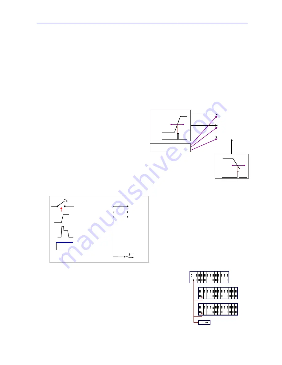
2.3.2. Triggers
The PowerSync Analyzer has extensive triggering capabilities, which are divided into 2 categories:
internal (or
waveform)
and
external (or event)
. The instrument also has the ability to perform non-triggered measurements. The
triggering types are depicted in Figures 2.7 and 2.8. Also
depicted in Figure 2.7 are trigger applications including
the DC meters, time-interval measurement, and load
current transient, each of which can be initiated with
those triggers.
Internal (or waveform) triggering is derived from the
common mode voltage levels received from the PSE
under test. For most measurements, this triggering is
based upon the trigger levels and directions (rising or
falling) set for
Trigger 1
. A second trigger,
Trigger 2
is
used exclusively for terminating time interval
measurements. Trigger 2 offers identical
programmability as Trigger 1 (levels and edge polarities).
External (or Event) triggering is also used to initiate
measurements or actions, and is initiated by either a user
command, an action that is programmed to send out an
external trigger, or through an external event that appears
on the trigger bus. The trigger bus is a trigger signal
connection that is shared by all ports within a system, and
by the Trig Out BNC connector on each PowerSync
Analyzer. Figure 2.8 shows the sources used to generate
External (or event) triggers on the left, and shows the
external bus configuration on the right.
Any External trigger in the system will appear on this bus,
and will trigger any
port which is
waiting for an external trigger event. This enables cross-triggering across ports
and triggering via externally generated signals. It also enables the user to use the
trigger output for other purposes, such as monitoring data throughput during PSE
powering or load transients.
The BNC trigger connector on the Chassis Controller front panel can be
configured as an output or an input. As an output, it directly mirrors the External
trigger bus. Output triggers will appear as a 3.3V, 10 mSec pulse. When set as
an input, it can drive the external trigger bus inside the PSA chassis. This
enables triggering across multiple instruments, which may be desirable when
testing equipment with more than 24 ports.
Vo
lt
a
g
e
Trigger 1
Level
DC Meters
Current Transient
Time Interval Meter
Internal Trigger
External Trigger
Vo
lt
a
g
e
Trigger 2
Level
Trigger 2
Vo
lt
a
g
e
Trigger 1
Level
DC Meters
Current Transient
Time Interval Meter
Internal Trigger
External Trigger
Vo
lt
a
g
e
Trigger 2
Level
Trigger 2
Figure 2.7
Test Port Triggering
Port Switch
(Connect or Isolate)
Cu
rre
nt
Cu
rre
n
t
Static Load Change
Load Transient
Software “TrigOut”
(or Send Trigger)
> trigout
Another Port
5 Sources
External
Trigger Bus
Slot1, Port1
Slot1, Port2
Slot2, Port1
…..
Chassis
Ext. Trigger
(Optional)
(Optional)
(Optional)
Port Switch
(Connect or Isolate)
Cu
rre
nt
Cu
rre
n
t
Static Load Change
Load Transient
Software “TrigOut”
(or Send Trigger)
> trigout
> trigout
Another Port
5 Sources
External
Trigger Bus
Slot1, Port1
Slot1, Port2
Slot2, Port1
…..
Chassis
Ext. Trigger
(Optional)
(Optional)
(Optional)
Figure 2.8
PSA Test Port Trigger Sources
PSA #1
PSA #2
PSA #3
PSA #4
E
x
ter
n
a
l T
ri
gger
PSA #1
PSA #2
PSA #3
PSA #4
PSA #1
PSA #2
PSA #3
PSA #4
E
x
ter
n
a
l T
ri
gger
Figure 2.9
External Trigger Bus
Summary of Contents for PowerSync PSA100
Page 26: ...PowerSync Analyzer Reference Manual March 9 2010 Sifos Technologies page 26 ...
Page 56: ...PowerSync Analyzer Reference Manual March 9 2010 Sifos Technologies page 56 ...
Page 84: ...PowerSync Analyzer Reference Manual March 9 2010 Sifos Technologies page 84 ...
Page 110: ...PowerSync Analyzer Reference Manual March 9 2010 Sifos Technologies page 110 ...
Page 120: ...PowerSync Analyzer Reference Manual March 9 2010 Sifos Technologies page 120 ...