


PowerSync Analyzer Reference Manual
March 9, 2010
Sifos Technologies page
29
The
Apply Settings
button will annunciate via
red
text that a change has been selected and must be applied.
The
Auto-Discover
button will cause the PowerSync Analyzer to automatically discover the proper ALT and Polarity
configuration of a connected PSE on the current slot-port, and then apply those settings across all ports associated with
the presently connected PowerSync Analyzer or across the multiple chassis’ associated with a PSA2400. These settings
may be retained in a PSE local configuration file through the
File Save
operation.
The
Connect Port
button creates a connection from the incoming PoE bus to the detection passives. The
Disconnect
Port
removes the detection passives from the bus. A PSE will not successfully detect and power-up a port unless the
detection passives are
connected
. Once the PSE port is powered, the detection passives automatically become invisible
to the PoE bus, however an AC MPS passive load of 24 K
Ω
then activates. This means that a PSE utilizing the AC
MPS method will not remove power unless the port is
disconnected
(or isolated). However, if the PSE is using the DC
MPS method, the absence or presence of the 24 K
Ω
AC MPS signature resistance will have no effect and the port will
remove power as soon as the static current load (
see Section 3.1.6
) drops below a threshold of 5 to 10 mA.
The Port Configuration menu also offers the ability to generate an
External Trigger
event when either the
Connect
Port
or
Disconnect Port
buttons are pressed. This trigger event will occur within several milliseconds of the actual
switch operation in the PSA test port. Checking the
Send Trigger
box will cause this behavior to occur and
deselecting it will inhibit External Trigger generation. (
See Section 2.3.2 for further information on triggering
.)
Users also have the option to simultaneously connect or disconnect all test ports within the currently addressed chassis
using the
Connect Port
and
Disconnect Port
buttons. Selecting the
Connect/Disconnect All Ports
checkbox will
enable the “broadcast” connection operation. Note that this operation will
not
span multiple chassis’ of a PSA2400
configuration.
3.1.3.
Slot-Port and Chassis Selection
PSA Interactive provides one or more menus with capability to route configurations and generate queries from selected
test ports and selected PSA chassis’s. Within these menus, the Slot and Port selection lists will only contain the valid
populated slots for the currently connected chassis. The Slot and Port may be selected by clicking on the slot and port
from the scrolled list or by typing a value into the entry field directly. Once a Slot and Port have been selected on
any
menu
, those values will persist as other menus or sub-menus are opened and closed. This provides an efficient means to
route configurations and queries at virtually any time and only when necessary. Whenever a new Slot and Port are
selected within any menu, the
Read Settings
button must be actuated to update the menu to current settings of the new
Slot and Port.
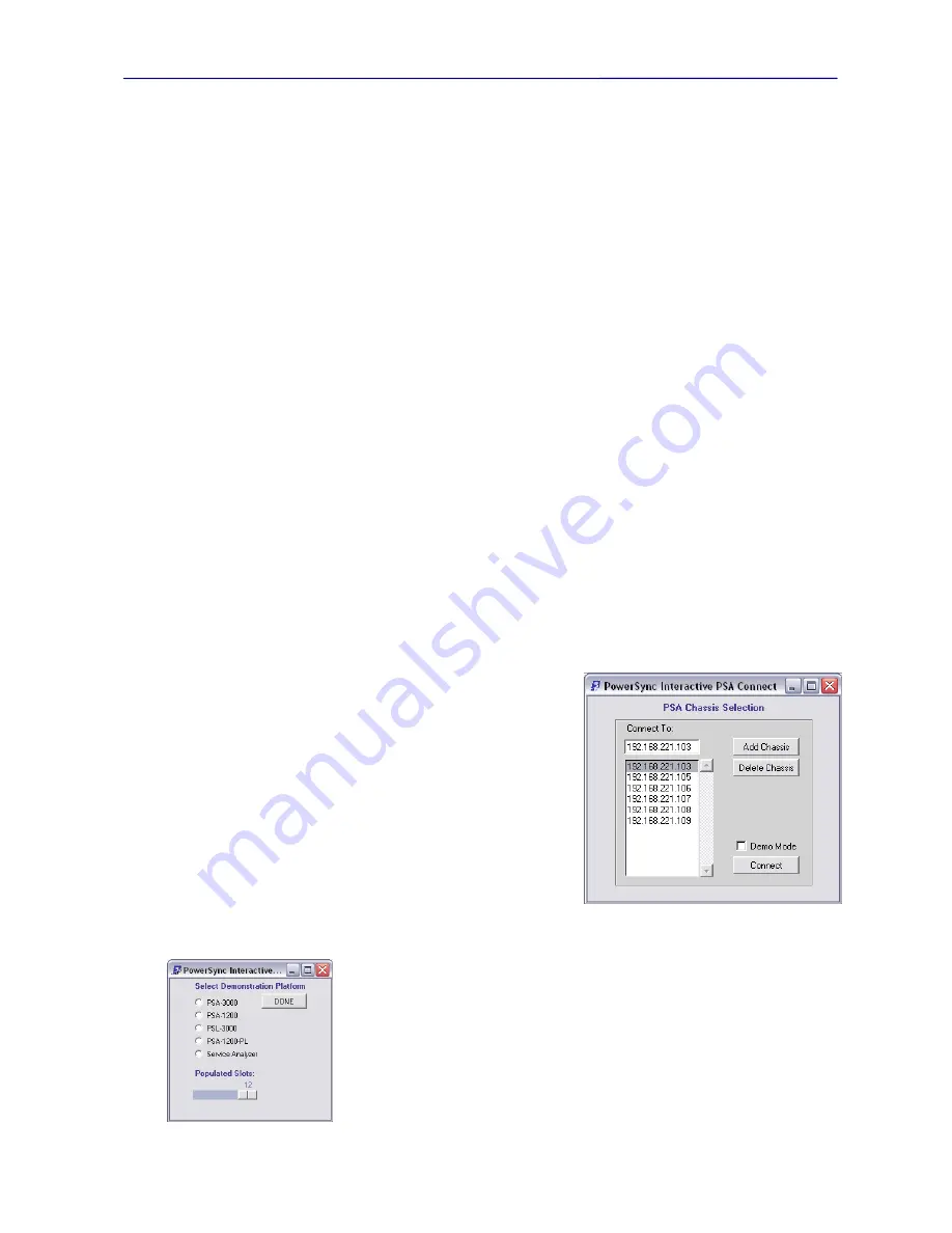
When the
Select Chassis
button is pressed, a window opens
(Figure
3.5)
with a scrolled list of all “known” PSA chassis IP addresses on the
LAN. This list of chassis addresses initially comes from the local
environment file (
see Section 2.4.4
). The list of known or available
chassis’ will be updated whenever PSA Interactive is started. It will
also be updated if a selected chassis is found
not
to exist on the LAN.
Users may add a chassis by entering the new chassis address in the
Select Chassis entry field, then pressing
Add Chassis
. If the entered
chassis is found on the LAN, it will be added to the list and become
available for future selection. It must then be
selected
from the list
before
pressing
Connect
to effect the PSA Interactive connection
change. The
Delete Chassis
button may be used to remove a chassis
address from the list of known addresses. This change will also be
retained in the local environment file.
The PSA Chassis Selection menu offers a checkbox for enabling or disabling
Demo
Mode
. When
Connect
ed in
Demo Mode
, PSA Interactive will present a menu
allowing users to select and then manage an imaginary PSA platform.
Demo Mode
will automatically be invoked upon entering PSA Interactive if no known PSA chassis’
are discovered on the LAN. Many PSA Interactive menus, standard PSE tests, and
operations will function in
Demo Mode
as if an actual PSA chassis and PSE ports were
connected.
Once a chassis is selected and appears in the entry field, simply press
Return
to retain
that new chassis address as the target recipient of configuration commands and queries.
Figure 3.5
PSA Chassis Selection Dialog
Summary of Contents for PowerSync PSA100
Page 26: ...PowerSync Analyzer Reference Manual March 9 2010 Sifos Technologies page 26 ...
Page 56: ...PowerSync Analyzer Reference Manual March 9 2010 Sifos Technologies page 56 ...
Page 84: ...PowerSync Analyzer Reference Manual March 9 2010 Sifos Technologies page 84 ...
Page 110: ...PowerSync Analyzer Reference Manual March 9 2010 Sifos Technologies page 110 ...
Page 120: ...PowerSync Analyzer Reference Manual March 9 2010 Sifos Technologies page 120 ...