background image


Fire & Security Products 

Siemens Building Technologies  


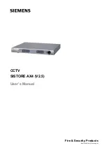
CCTV 

SISTORE AX4 (V2.5) 

User’s Manual 


Summary of Contents for SISTORE AX4

Page 1: ...Fire Security Products Siemens Building Technologies CCTV SISTORE AX4 V2 5 User s Manual ...

Page 2: ...ne unsere vorgängige schriftliche Ermächtigung ganz oder teilweise Dritten zugänglich machen oder außerhalb des Zweckes verwenden zu dem es ihm übergeben worden ist We reserve all rights in this document and in the subject thereof By acceptance of the document the recipient acknowledges these rights and undertakes not to publish the document nor the subject thereof in full or in part nor to make t...

Page 3: ... Network Port 3 2 11 Connecting to the Modem Port 3 2 12 Connecting to the RS 232C Port 3 2 13 Factory Reset 3 2 14 Connecting to the USB Port 3 2 15 Connecting the Power Cord 3 3 Configuration 3 3 1 Front Panel Controls 3 3 1 1 Power LED 3 3 1 2 Network LED 3 3 1 3 Backup LED 3 3 1 4 Camera Buttons 1 to 4 3 3 1 5 Quad Seq Button 3 3 1 6 Menu Button 3 3 1 7 PTZ Button 3 3 1 8 Panic Button 3 3 1 9 ...

Page 4: ...ext In Event Action Notify Setup Screen 3 3 8 10 Video Loss Event Action Record Setup Screen 3 3 8 11 Video Loss Event Action Alarm Out Setup Screen 3 3 8 12 Video Loss Event Action Notify Setup Screen 3 3 9 Display Setup 3 3 9 1 OSD On Screen Display Setup 3 3 9 2 Main Monitoring Setup Screen 3 3 10 Network Setup Screen 3 3 10 1 LAN Setup Screen 3 3 10 2 Modem Setup 3 3 10 3 Callback Center LAN S...

Page 5: ...on 3 5 1 Preparing the USB IDE hard disk drive in Windows 2000 3 5 2 Preparing the USB IDE hard disk drive in Windows 98 3 6 Appendix B Troubleshooting 3 7 Appendix C Connector Pin Outs 3 7 1 I O Connector Pin Outs 3 7 2 RS485 Connector Pin Outs 3 8 Appendix D Map of Screens 3 9 Appendix E Specifications 3 10 Keyword index 3 ...

Page 6: ......

Page 7: ...ideo Sources l Multiple Search Engines Date Time Calendar Event l Records up to 120 NTSC Images per Second 100 PAL Images per Second l Loop Through Video Connectors l Continuous Recording in Disk Overwrite Mode l Continues Recording while Archiving Transmitting to Remote Site and during Playback l User friendly Graphical User Interface GUI Menu System l Various Record Modes Time Event Pre event an...

Page 8: ...iew video after selecting the time or event Your DVR can be set up for event or time lapse recording You can define times to record and the schedule can change for different days of the week and user defined holidays The DVR can be set up to alert you when the hard disk drive is full or it can be set up to record over the oldest video once the disk is full Your DVR uses a proprietary encryption sc...

Page 9: ...e Loop BNC unless it is connected to another terminated device because it will cause poor quality video 2 5 Connecting Audio NOTE It is the user s responsibility to determine if local laws and regulations permit recording audio Fig 5 Audio In and Out connectors Your DVR can record audio Connect the audio source to Audio In Connect Audio Out to your amplifier NOTE The audio input is from an amplifi...

Page 10: ...onitor to either the Video Out or SVHS Out connector NOTE For SPOT monitor Output set the CVBS SVHS VGA selector switch to the CVBS SVHS NOTE If your monitor has an SVHS input use it because it will give you better quality video display NOTE The Video Out BNC and the SVHS Out connectors may be connected to individual monitors for simultaneous operation 2 7 2 Connecting the RGB Monitor Fig 8 VGA co...

Page 11: ...used to reset both the Alarm Out signal and the DVR s internal buzzer Mechanical or electrical switches can be wired to the ARI Alarm Reset In and GND Ground connectors The threshold voltage is below 0 3V and should be stable at least 0 5 seconds to be detected Connect the wires to the ARI Alarm Reset In and GND Ground connectors 2 8 4 Alarm Out Fig 10 Alarm Output connector strips The DVR can act...

Page 12: ... See Chapter 3 Configuration for configuring the modem connections CAUTION To reduce the risk of fire use only No 26 AWG or larger UL Listed or CSA Certified Telecommunication Line Cord 2 12 Connecting to the RS 232C Port Fig 14 RS 232C connector An RS 232C port is provided to connect an external modem for remote monitoring configuration and software upgrades text input and to connect a remote con...

Page 13: ...RW drives or flash drives for archiving video Position the external hard disk drive close enough to the DVR so that you can make the cable connections usually less than 6 feet Use the USB cable provided with the hard disk drive or CD RW to connect it to the DVR See Chapter 4 Operation for archiving video to an external USB IDE hard disk drive USB CD RW drive or USB flash drive You also can upgrade...

Page 14: ...ated However when you are in the menu or PTZ mode you have to exit the menu or PTZ mode first to reset alarmoutput 3 1 1 Power LED The Power LED is lit when the DVR is On 3 1 2 Network LED The Network LED is lit when the unit is connected with RAS Remote Administration System either via Ethernet or modem 3 1 3 Backup LED The Backup LED is lit when data is being backed up using the USB port 3 1 4 C...

Page 15: ... zoom mode directly Pressing the PTZ button in the playback mode enters the digital zoom playback mode NOTE When the DVR is in the PTZ mode a white line will display around the image NOTE In the digital zoom mode and digital zoom playback mode a bright small box is laid over the image The box indicates the spot to be enlarged 3 1 8 Panic Button Pressing the Panic button activates panic recording s...

Page 16: ... speed from and The screen displays and respectively Entering Playback mode from Live Monitoring mode can be user password protected 3 2 Turning on the Power Connecting the power cord to the DVR turns on the unit The unit will take approximately 60 seconds to initialize 3 3 Initial Unit Setup Before using your DVR for the first time you will want to establish the initial settings This includes ite...

Page 17: ...hlight the box beside Audio Recording and select either On or Off NOTE It is the user s responsibility to determine if local laws and regulations permit recording audio Highlight the box beside Sequence Dwell Time and select from 3 to 60 seconds for the camera sequence dwell time Selecting System Information enters a screen where you can set up system information Selecting Storage Check enters a s...

Page 18: ...ibed above The Normal Setup screen gives you access to all the DVR s setup screens 3 5 1 System Information Highlight System Information and press the button The System Information screen appears Fig 22 System Information screen In the System Information screen you can name the site location assign a unit ID number select the language to use and upgrade the software Highlight Change and press the ...

Page 19: ...y highlighting it and using the arrow buttons to increase and decrease the numbers The Unit ID number is used to identify the unit when it is networked with other DVRs You cannot use the same number for two or more DVRs that are within the same network Highlight the box beside Language and press button A dropdown menu displays the available languages Highlight the desired language and press the bu...

Page 20: ... can save your changes by highlighting OK and pressing the button Selecting Cancel exits the screen without saving the changes 3 5 2 Date Time Setup Highlight Date Time in the Main menu and press the button The Date Time setup screen appears Fig 26 Date Time setup screen CAUTION If you set a date and time that is older than some of your recorded images any images with dates and times later than th...

Page 21: ...f Highlight the Holiday Setup box and press the button You can set up holidays by highlighting Add and pressing the button The current date appears Highlight the month and day and change them by using the arrow buttons Press the button to add the date Dates can be deleted by highlighting the X beside the date and pressing the button NOTE Holidays that do not fall on the same date each year should ...

Page 22: ...n selecting Now any video with a later time and date will be lost if the time and date of a time server is earlier than the last recorded image of the DVR NOTE When the time difference between the DVR and the time server is more than one minute the DVR might not synchronize the time to prevent any unexpected loss of recorded video data If you want to synchronize the time manually select Now Highli...

Page 23: ...the designated time Highlight the box under the Interval heading and press the button A slide bar appears allowing you to set the check interval from 1 Hour to 30 Days The Status field displays the fault conditions When it is Good there was recording or an alarm occurred during the designated time When it is Bad there was no recording or no alarm occurred during the designated time Highlight the b...

Page 24: ...screen displays replacing the hard disk drive is recommended usually within 24 hours NOTE The S M A R T Monitoring Information screen appears only in the monitoring mode The C field displays the temperature of the storage device The Usage field displays the device usage The DVR can be set to react to storage problems by activating an internal buzzer or external alarms display the warning message a...

Page 25: ...t Check Now and press the button You can save your changes by highlighting OK and pressing the button Selecting Cancel exits the screen without saving the changes 3 5 5 System Log Screen Highlight System Log in the Main menu and press the button The System Log screen appears Fig 32 System Log screen The System Log screen displays a record of various events logged by the DVR The list shows the date...

Page 26: ...heading and pressing the button Select the On Off Covert 1 or Covert 2 from a drop down list NOTE When selecting the Covert 1 the DVR displays the camera title and status icons on the covert video When selecting the Covert 2 the DVR displays only camera title on the covert video You can assign titles to each camera by highlighting the Title heading and pressing the button A virtual keyboard allows...

Page 27: ...s The PTZ ID number can be set from 0 to 256 3 6 2 Alarm In Setup Screen Highlight Alarm In in the Main menu and press the button The Alarm In setup screen appears Fig 36 Alarm In setup screen The alarm terminal strip on the back of the DVR has inputs associated with each alarm You can set up each input on the Alarm In Setup screen You can turn each input On via Alarm I O or Camera Alarm or Off Ea...

Page 28: ...the image where you want to detect motion e g a doorway Highlight the icon under the Zone heading and press the button The Motion Detection Zone screen will display Fig 38 Motion Detection Zone screen The Motion Detection Zone screen is laid over the video for the selected camera You can set up motion detection zones by selecting or clearing blocks The menu on the setup screen has the following fu...

Page 29: ...ield and reports the text in information in the event log Highlight the box beside keyword 2 and press the button to display a virtual keyboard Enter the second keyword for transaction field detection Highlight the box beside Delimiter and pressing the button displays a virtual keyboard Enter the character string that divides each text in line The line feed character J has been entered as a defaul...

Page 30: ...0 minute increments from 0 00 to 24 00 Fig 41 Alarm Out Schedule screen You can select individual blocks of time entire days of the week entire blocks of time or the entire schedule Select a specific block of time by highlighting it Select an entire day by highlighting the day of the week or Holiday on the left of the screen Select an entire block of time by highlighting the time at the top of the...

Page 31: ...OT play live or recorded audio The DVR supports 4 Audio inputs You can set up each input on the Audio Setup screen When it is On the DVR will play live audio through the attached speaker when it displays live video Move to the Audio In field and highlight the box under On Off heading and press the button This toggles between On and Off You can save your changes by highlighting OK and pressing the ...

Page 32: ...it and Stop Bit for the device you are connecting to the DVR For RS232 it is possible to select Remote Control External Modem or Text In in the Usage field For RS485 it is possible to select either Remote Control or PTZ Control in the Usage field NOTE Selecting the External Modem in the RS232 field only defines the RS 232C port as being used for external modem connections Refer to Modem Setup scre...

Page 33: ...the button This toggles between Overwrite and Stop When in the Overwrite mode the DVR continues recording when the hard disk drive is full by overwriting the oldest video When in the Stop mode the DVR stops recording when the hard disk drive is full If the DVR is set to the Stop mode you can set it to beep or activate the Alarm Out port when the hard disk drive is full Highlight the box beside On ...

Page 34: ...der the Speed heading and press the button A drop down list of record speeds appears You can select from 0 5 ips to 30 ips 25 ips for PAL NOTE You cannot s elect 30 ips 25 ips for PAL for High Resolution Highlight the box under the Quality heading and press the button A drop down list appears You can select from Very High High Standard and Low image quality All other variables being equal Very Hig...

Page 35: ...dividual block and toggle it On or Off by pressing the button l You can change a 30 minute segment for all days by placing the cursor on the time line and pressing the button to toggle the segment On or Off l You can change an entire day by placing the cursor on the day of the week and pressing the button to toggle the day On or Off l You can change the entire calendar by placing the cursor in the...

Page 36: ... pre event recording The image speed can be set from 0 5 to 30 ips 25 ips PAL and image quality can be selectable from High Standard and Low NOTE The pre event recording speed is 30 images per second 25 ips for PAL when the resolution is set to Standard However when set toHigh the recording speed will be decreased to 15 images per second 12 5 ips for PAL You can set the amount of time to record pr...

Page 37: ...can be assigned a schedule camera recording speed video quality and dwell time Fig 48 Alarm In Event Action Record setup screen Highlight the Sched box and press the button A schedule screen appears Set the schedule as described earlier Highlight the Camera box and press the button A camera selection screen appears Select the camera number you would like to associate with the sensor NOTE You can a...

Page 38: ...x and either Beep or the alarm output terminal that you want to associate with the sensor Highlight the Dwell Time box and set the length of time you want the output activated 3 8 3 Alarm In Event Action Notify Setup Screen The DVR can be set to notify the remote site when certain events are activated Fig 50 Alarm In Event Action Notify setup screen Highlight the Sched box and press the button A s...

Page 39: ...on A schedule screen appears Set the schedule as described earlier Highlight the Camera box and press the button A camera selection screen appears Select the camera number you would like to associate with the camera NOTE You can associate multiple cameras with a camera that detects motion Highlight the Speed box and select number of images per second you would like to record from the drop down men...

Page 40: ...nd either Beep or the alarm output terminal that you want to associate with the motion event Highlight the Dwell Time box and set the length of time you want the output activated 3 8 6 Motion Detector Event Action Notify Setup Screen The DVR can be set to notify the remote site when certain motion events are activated Fig 53 Motion Detector Event Action Notify setup screen Highlight the Sched box ...

Page 41: ...ched box and press the button A schedule screen appears Set the schedule as described earlier Highlight the Camera box and press the button A camera selection screen appears Select the camera number you would like to associate with the text in device NOTE You can associate multiple cameras with a text in device Highlight the Speed box and select number of images per second you would like to record...

Page 42: ...eep or the alarm output terminal that you want to associate with the text in device Highlight the Dwell Time box and set the length of time you want the output activated 3 8 9 Text In Event Action Notify Setup Screen The DVR can be set to notify the remote site in the case of text in Fig 56 Text In Event Action Notify setup screen Highlight the Sched box and press the button A schedule screen appe...

Page 43: ...ton A schedule screen appears Set the schedule as described earlier Highlight the Camera box and press the button A camera selection screen appears Select the camera number you would like to associate with the camera that has lost video NOTE You can associate multiple cameras with a camera Highlight the Speed box and select number of images per second you would like to record from the drop down me...

Page 44: ...rlier Highlight the Alarm Out box and either Beep or the alarm output terminal that you want to associate with the camera that has lost video 3 8 12 Video Loss Event Action Notify Setup Screen The DVR can be set to notify the remote site in the case of video loss Fig 59 Video Loss Event Action Notify setup screen Highlight the Sched box and press the button A schedule screen appears Set the schedu...

Page 45: ... screen Highlight the box beside Date and press the button to toggle the date display On and Off Highlight the box beside Time and press the button to toggle the time display On and Off Highlight the box beside Title and press the button to toggle the camera title display On and Off Highlight the box beside Status and press the button to toggle status display On and Off Highlight the box beside Le...

Page 46: ...box beside Sequence Dwell Time and press the button You can adjust the sequence dwell time from 3 to 60 seconds NOTE The DVR does not sequence the camera having video loss Highlight the box beside Event Monitoring and press the button to toggle between On and Off When it is On video from the lowest camera number among those connected with the event detected sensor will be displayed full screen on ...

Page 47: ... They are different from the Admin and User passwords for the DVR itself NOTE The passwords are case sensitive The factory default password for both Administrator and User is 12345678 CAUTION Write the password down and keep it in a safe place Once the password has been reset the default will no longer work If the password is forgotten the unit must be reset using the Factory Reset Button and all ...

Page 48: ...DVR might be changed whenever turning the DVR on You can check the current IP address of the DVR in the System Information screen Change the numbers by highlighting them and using the arrow buttons to increase or decrease the numbers NOTE You will need to get the appropriate IP Address Gateway and Subnet Mask from your network administrator The factory default LAN settings are l IP Address 192 168...

Page 49: ... beside Data Bit and press the button This toggles between 7 bit and 8 bit formats Highlight the box beside Stop Bit and press the button This toggles between 1 and 2 Stop Bits Highlight the box beside Parity and press the button A drop down list appears You can select from None Odd or Even parity You can save your changes by highlighting OK and pressing the button Selecting Cancel exits the scree...

Page 50: ...e box beside Retry and enter the number of times you would like the DVR to try contacting the computer You can select from 1 to 10 retries Highlight the box beside E mail notification and press the button to toggle between On and Off Highlight the box beside SMTP Server IP and enter the SMTP server IP address obtained from your system administrator Highlight the box beside E mail recipient and ent...

Page 51: ... will be used to contact the DVR from a remote site Highlight the box beside Retry and enter number of times you would like the DVR to try contacting the computer You can select from 1 to 10 retries NOTE When any event occurs the DVR will call a remote site to give notice of an event The DVR will hold the phone line for 30 seconds after connecting a remote site to wait for other events that might ...

Page 52: ...by first entering the current password entering a new password and finally confirming the new password To change the password highlight the Password box and press the button A window appears asking you to enter the current password If you enter the correct password another window appears asking you to enter a new password using the camera buttons After you press the button another screen appears a...

Page 53: ...the external drive for back up Fig 69 Clip Copy screen To select the type of the drive to use for back up highlight the box on the top and press the button A drop down list of available drives appears You can select USB HDD USB CD RW or USB Flash Memory If you want to archive audio with video place a checkmark in the Audio box You can define how much video to back up by changing the start and end ...

Page 54: ...have been scratched or damaged in any way CAUTION Do NOT disconnect the USB cable or the power from the external drive while backing up video If the external drive is shut down or the USB cable is disconnected while backing up THE DVR SYSTEM MAY NOT WORK NORMALLY OR THE EXTERNAL DRIVE COULD BE DAMAGED and you will get an error message the next time you try to back up You will need to power down th...

Page 55: ...ompletes its initialization process it will begin showing live video on the attached monitor and playing live audio through the attached speaker The default mode is to display 4 cameras at once Pressing any camera button will cause that camera to display full screen It displays live video and plays live audio until the user enters another mode Pressing the Quad Seq button toggles between quad 2x2 ...

Page 56: ...ssing the Menu button in the PTZ mode displays the PTZ Menu screen Fig 70 PTZ Menu l Set Preset Sets the Presets for PTZ camera l Quit Closes the menu 4 2 2 Set Preset Once you have the camera at the desired settings you can save camera position settings as presets so that you can go directly to desired views Select Set Preset in the PTZ Menu Select the number you want to assign to the preset and ...

Page 57: ...ory default is Stop when the hard disk drive is full The DVR can be set to continue recording Overwrite once the hard disk drive is full It does this by recording over the oldest video Although you will be able to record without changing the unit from its original factory settings you will want to take advantages of the DVR s many tools See Chapter 3 Configuration for detailed descriptions of the ...

Page 58: ...ons Pressing the left arrow button plays video backward at high speed Pressing the button again toggles the playback speed from and The screen displays and respectively Pressing the right arrow button plays video forward at high speed Pressing the button again toggles the playback speed from and The screen displays and respectively After selecting Enter Pause press the up arrow button to advance t...

Page 59: ...orded audio may be interrupted occasionally 4 5 5 Digital Zoom Playback Mode You can enter the Digital Zoom Playback mode by pressing the PTZ button in the Playback mode Once you press the PTZ button in the playback mode the image pauses and a bright small box is laid over the image This box indicates the spot to be enlarged Move the position of the box using the arrow buttons and press the button...

Page 60: ...ee below for more details 4 6 1 Date Time Search Fig 77 Date Time Search screen Move the cursor over the date and press the button Adjust the numbers using arrow buttons Once you have set the date you want to search for video press the button Move the cursor over the time and press the button Adjust the numbers using arrow buttons Once you have entered the time you want to search for video press t...

Page 61: ... was recorded for the entire hour Once you have set the date and time you want to search highlight the GO button and press the button The selected date and time will display The arrow buttons can now be used to review the surrounding video 4 6 3 Event Search Fig 79 Event Log screen The DVR maintains a log of each time the Alarm Input port is activated The Event Log screen displays this list Highli...

Page 62: ...elect the Search by Camera select the target cameras and event options When you select the Search by Event select event options for each device NOTE When selecting Text In as the event option search text in events that have the identical value to any specific transaction number entered in the Transaction field Otherwise search all text in events when the Transaction field is empty Once you set you...

Page 63: ...y right clicking on the icon and checking under Properties General File System If the file system is NOT FAT32 format format the USB IDE hard disk drive using the FAT32 format 5 If the USB IDE hard disk drive is not partitioned go to Administrative Tools in Control Panel and launch Computer Management Open Disk Management in Storage and right click an unallocated region of the USB IDE hard disk dr...

Page 64: ... format the USB IDE hard disk drive with FAT32 format 5 Run the FDISK utility by clicking Start then RUN Type fdisk and click OK 6 When the MS DOS command prompt appears type Y and hit the enter key 7 In the FDISK Option menu choose 5 Change current fixed disk drive 8 Choose the appropriate letter corresponding to the USB IDE hard disk drive 9 In the FDISK Option menu choose 1 Create DOS partition...

Page 65: ... the Loop connector make certain it is connected to a properly terminated device DVR has stopped recording If hard disk drive is full you will either need to delete video or set the DVR to the Overwrite Mode DVR displays an error message stating that the last recorded image date and time is later than the current date and time setting of the DVR The DVR will automatically reset the time and date o...

Page 66: ...Products 09 2004 7 Appendix C Connector Pin Outs 7 1 I O Connector Pin Outs Fig 82 Input Fig 83 Output AI 1 to 4 Alarm Inputs 1 to 4 GND Chassis Ground ARI Alarm Reset In NC Normally Closed C Common NO Normally Open 7 2 RS485 Connector Pin Outs Master Unit Slave Unit RX TX To TX RX RX TX To TX RX ...

Page 67: ...Appendix D Map of Screens 67 Siemens Building Technologies SISTORE AX4_EN doc Fire Security Products 09 2004 8 Appendix D Map of Screens ...

Page 68: ... RS 232C for external modem Audio Input 4 lines in Audio Output 1 line CONNECTORS Video Input Composite 4 BNC Video Loop Composite 4 BNC Monitor Output Composite 1 BNC SVHS 1 Y C Analog RGB 1 VGA Audio In 4 RCA connector Audio Out 1 RCA connector Alarms Terminal block Alarm Reset In Terminal block Modem Port RJ 11 Ethernet Port RJ 45 RS 232C Serial Port DB9 P RS 485 Serial Port 4 connector termina...

Page 69: ...6 Initial Unit 16 Installation 8 Installation Tools 8 L LAN Setup 48 Live Monitoring 55 Loop Through Video 9 M Main Monitoring Setup 46 Map of Screens 67 Modem Port 12 Modem Setup 49 Monitor 10 N Network Port 12 Network Setup 47 Normal Setup 18 O Operation 55 OSD On Screen Display Setup 45 P Package Contents 8 Password 16 52 Playing Recorded Video 58 Power Cord 13 Q Quick Setup 17 R Record Mode Se...

Page 70: ...uhe www sbt siemens com fsp 2004 Copyright by Siemens Building Technologies AG Data and design subject to change without notice Supply subject to availability Printed in the Federal Republic of Germany on environment friendly chlorine free paper Document no A24205 A336 B501 Edition 09 2004 ...

Reviews: