3.3
Interfaces to select the safety functions
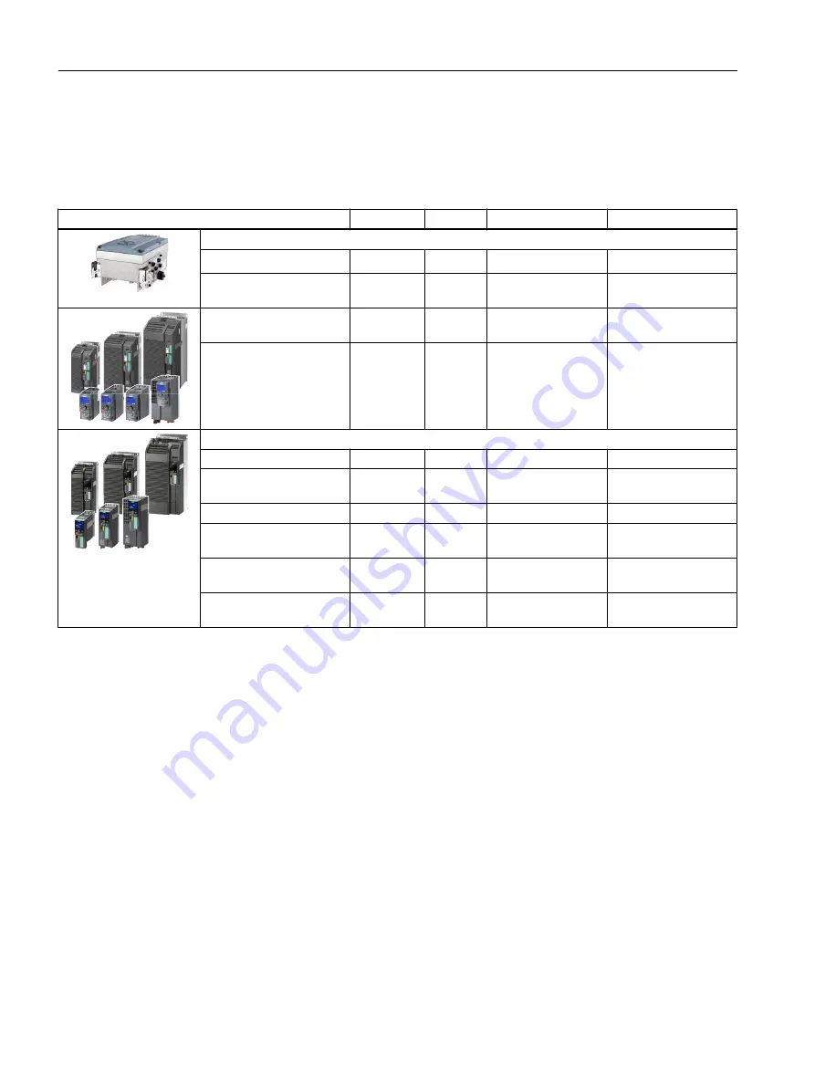
Depending on the inverter, the safety function interfaces are fail-safe digital inputs and outputs
(F‑DI, F‑DO), safety-related fieldbus communication PROFIsafe - and a fail-safe digital output
to control a brake.
Inverter
F-DI
F-DO
PROFIsafe
Safe brake control
SINAMICS G110M with Control Unit …
CU240M USS
1
---
1)
---
---
CU240M DP
CU240M PN
1
---
Telegram 30
3)
---
SINAMICS G120C USS
SINAMICS G120C CAN
1
---
---
---
SINAMICS G120C DP
SINAMICS G120C PN
1
---
Telegram 30
3)
---
SINAMICS G120 with Control Unit …
CU240E‑2
1 + 1
5)
---
---
---
CU240E‑2 DP
CU240E‑2 PN
1 + 1
5)
---
Telegram 30
3)
---
CU240E‑2 F
3 + 1
5)
---
---
---
CU240E‑2 DP‑F
CU240E‑2 PN‑F
3 + 1
5)
---
Telegram 30
3)
, Tele‐
gram 900
4)
---
CU250S‑2
CU250S‑2 CAN
3 + 1
5)
1
---
With Safe Brake Re‐
lay
CU250S‑2 DP
CU250S‑2 PN
3 + 1
5)
1
Telegram 30
3)
, Tele‐
gram 900
4)
With Safe Brake Re‐
lay
1)
--- Not available
2)
The inverter evaluates the F0 rail in the backplane bus of the ET 200pro system via an internal fail-safe digital input. The
ET‑200pro F‑RSM and F‑Switch modules control the F0 rail.
3)
Telegram 30 for control and for the status feedback signal from the safety functions
4)
Telegram 900: Function as for telegram 30 and additional feedback signal of the F-DI status
5)
In addition to the fail-safe digital inputs of the Control unit, an additional fail-safe digital input is available for the STO function
on PM240-2 FSD … FSF and PM240P-2 FSD … FSF Power Modules.
Description
3.3 Interfaces to select the safety functions
Safety Integrated - SINAMICS G110M, G120, G120C, G120D and SIMATIC ET 200pro FC-2
24
Function Manual, 01/2017, FW V4.7 SP6, A5E34261271B AD


