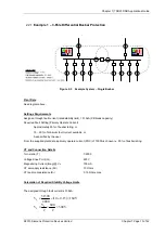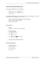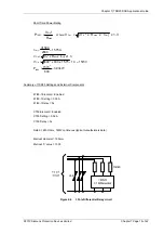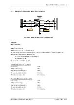
Chapter 7) 7SR23 DAD Applications Guide
©2013 Siemens Protection Devices Limited
Chapter 7 Page 20 of 42
3.1
CT Location Considerations
The position of CTs for busbar protection varies according to the design of the switchgear.
The switchgear design may include CTs which are installed on both sides of the CBs facilitating zones of
protection that overlap the CBs. Many MV switchgear designs however have CTs on only one side of the CB
creating protection zone ‘blind spots’. Examples of CT locations are shown below.
3.1.1
CTs Overlapping Circuit Breakers
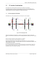
With reference to fig. 3.1 the protection performance for the faults F1 to F6 is considered.
Figure 3-1 CTs Overlapping the CBs
Where CTs, and therefore zones of protection, overlap the circuit breakers then the areas of primary plant
between the CTs and CBs are protected by more than one high speed protection system e.g. F3 and F4 in Figure
3-1.
Fault F1 is a busbar 1 fault which is cleared by busbar zone 1 protection.
Fault F2 is a busbar 2 fault and is cleared by busbar zone 2 protection.
F3 and F4 are busbar faults but due to their position they will cause both zone 1 and zone 2 protections to
operate, however zone 1 or zone 2 is unnecessarily tripped out of service, this disadvantage is acceptable in view
of the low incidence of such faults.
F5: Cleared by both the busbar and circuit protections.
F6: is a circuit fault but because of its position it causes both the busbar and circuit protections to operate. The
fault will be cleared, however busbar zone 1 will be unnecessarily tripped out of service. This disadvantage is
acceptable in view of the low incidence of such faults
.
Summary of Contents for 7SR23 DAD
Page 1: ...Answers for energy 7SR23 DAD High Impedance Protection Relay Reyrolle Protection Devices ...
Page 2: ......
Page 4: ...7SR23 DAD Contents 2013 Siemens Protection Devices Limited ...
Page 60: ...Chapter 3 7SR23 DAD Performance Specification 2013 Siemens Protection Devices Limited ...
Page 225: ......

