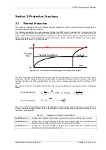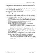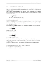
7SR105 Rho Description of Operation
©2018 Siemens Protection Devices Chapter 1 Page 26 of 57
the equivalent thermal current calculated by the relay is less than the thermal pickup setting. Once the equivalent
thermal current exceeds the thermal pickup setting the relay operates on the Cold thermal curve.
The purpose of the H/C ratio is to allow for the fact most motors are designed thermally to withstand the onerous
starting conditions rather than the running conditions. This leads to the fact the motors will tend to run at a much
lower temperature than their insulation class allows when thermal equilibrium is reached.
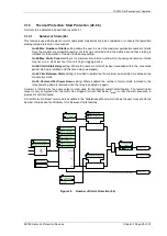
The thermal algorithm uses ‘hot’ and ‘cold’ curves, it also uses alternate time constants during different phases of
motor operation, to summarise:
T
START
T
HEAT
T
COOL
I
START
I
STOP
I
OVERLOAD
‘Hot’
Curve
‘Cold’
Curve
Thermal Time Constants
IEC Thermal Curve
Current Setting
Figure 3.1-3 Application of Thermal Overload Time Constants
Gn 49 Capacity Alarm
An alarm can be given if the thermal state of the system exceeds a specified percentage of the protected
equipment’s thermal capacity setting. This can be used to warn the operator that a relay thermal trip will occur if
this level of motor current continues.
Gn 49 Load Alarm
An alarm is available to provide warning of a sudden increase in load. The
Load Increase Alarm
setting is set as
a multiple of the thermal overload setting I
θ
.
Gn 49 Overload Alarm
An instantaneous alarm output is given if the equivalent thermal current I
e
exceeds the thermal overload setting I
θ
whilst the motor is in it running state.
Gn 49 Restart Inhibit Mode
The restart inhibit feature can be assigned to an output contact which can be used to prevent the motor from
being started until sufficient thermal capacity is available. A normally closed contact can be connected in the
motor starting circuit, thus breaking the circuit when the restart inhibit feature registers thermal state available.
A user thermal capacity value can be used (
Gn 49 Thermal Restart Inhibi
t setting).
Alternatively this can be set
‘Auto’ the relay then uses the value recorded from the previous start plus 15% safety margin.
Gn 49 Thermal Restart Mode
When ‘Restart Inhibit Mode’ is set to Auto then the motor restart can be inhibited until the relay determines that
sufficient time or capacity or ca time is available to allow the start.
Gn 49 Restore After Power Down
Where enabled the relay will indicate the thermal state prior to auxiliary supply removal when the auxiliary supply
is re-applied. When disabled the relay thermal state will be reset (0%) when the auxiliary supply is re-applied.
Summary of Contents for 7SR105 Rho
Page 1: ...Answers for energy 7SR105 Rho User Manual Motor Protection Relay Reyrolle Protection Devices ...
Page 2: ...Siemens Protection Devices 2 ...
Page 95: ...7SR105 Rho Technical Manual Chapter 4 Page 2 of 70 2018 Siemens Protection Devices ...
Page 99: ...7SR105 Rho Technical Manual Chapter 4 Page 6 of 70 2018 Siemens Protection Devices ...
Page 127: ...7SR105 Rho Technical Manual Chapter 4 Page 34 of 70 2018 Siemens Protection Devices ...
Page 153: ...7SR105 Rho Technical Manual Chapter 4 Page 60 of 70 2018 Siemens Protection Devices ...
Page 155: ...7SR105 Rho Technical Manual Chapter 4 Page 62 of 70 2018 Siemens Protection Devices ...
Page 157: ...7SR105 Rho Technical Manual Chapter 4 Page 64 of 70 2018 Siemens Protection Devices ...

