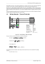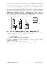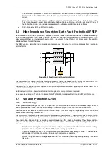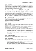
7SR105 Rho and 7SR17 Rho Applications Guide
©2018 Siemens Protection Devices
Chapter 7 Page 15 of 31
minutes
96
.
2
0.9
4.3
4.3
ln
8/60
I
I
I
ln
t
TauH
2
2
2
2
θ
2
2
=
−
=
−
=
As the safe stall time from cold (CSST) is 11 seconds, the TauH value could be set to 4 minutes e.g.
minutes
4
.
4
0.86
4.3
4.3
ln
11/60
I
I
I
ln
t
TauH
2
2
2
2
θ
2
2
=
−
=
−
=
The safe stall time from hot (HSST) i.e. 7 seconds gives a T
HEAT
value of 2.8 minutes. For this lower value a
setting of 2.5 could be chosen, there is the possibility of nuisance tripping after the motor has been in service for
some time with longer run-up times and higher currents.
A setting of TauH = 4 minutes is preferred allowing two starts in quick succession.
Starting Time Constant T
START
This time constant has not been provided set to 1.0 x TauH.
Cooling Time Constant T
COOL
In this example, the cooling time constant has not been specified either as a time constant or as a multiple of its
heating time constant. We will therefore choose 10x, which is the default.
Hot/Cold Curve Ratio Setting (Hot Spot Weighting)
In our example the hot/cold stall withstand time ratio is 7/11 = 0.64 i.e. H/C setting = 64%. Note that at steady
state full load current the relay will stabilize at ‘Thermal Capacity Used’ of 36% with this setting applied.
Example:
Motor FLC
100A
Actual motor current
80A
HSST
7 seconds
CSST
11 seconds
The thermal capacity used can be determined from the
Hot/Cold Curve Ratio
as follows:
(
)
(
)
%
24
%
70
%
100
100
80
/
%
100
%
64
100
sec
11
sec
7
100
/
=
−
×
=
−
×
=
∴
=
×
=
×
=
A
A
RATIO
CURVE
COLD
HOT
FLC
current
motor
actual
used
capacity
Thermal
Cold
LRT
Hot
LRT
Ratio
Curve
Cold
Hot
Capacity Alarm Setting
An output can be configured to indicate that a selected thermal state level has been exceeded.
Typically this would be set to 95%. Of the thermal model
Load Alarm Setting
This current setting can be used to indicate abnormally high loading conditions e.g. 1.0 x Itheta.
Thermal Restart Inhibit Setting
This can be initially set to 50% in the absence of further information.
During commissioning, before starting the protected motor, check the thermal state at the motor by accessing the
“Thermal Capacity Used” meter and note the value. The motor should then be started with its normal load and,
when up to speed the “Thermal Capacity Used” value can be re-checked. The difference between these two
Summary of Contents for 7SR105 Rho
Page 1: ...Answers for energy 7SR105 Rho User Manual Motor Protection Relay Reyrolle Protection Devices ...
Page 2: ...Siemens Protection Devices 2 ...
Page 95: ...7SR105 Rho Technical Manual Chapter 4 Page 2 of 70 2018 Siemens Protection Devices ...
Page 99: ...7SR105 Rho Technical Manual Chapter 4 Page 6 of 70 2018 Siemens Protection Devices ...
Page 127: ...7SR105 Rho Technical Manual Chapter 4 Page 34 of 70 2018 Siemens Protection Devices ...
Page 153: ...7SR105 Rho Technical Manual Chapter 4 Page 60 of 70 2018 Siemens Protection Devices ...
Page 155: ...7SR105 Rho Technical Manual Chapter 4 Page 62 of 70 2018 Siemens Protection Devices ...
Page 157: ...7SR105 Rho Technical Manual Chapter 4 Page 64 of 70 2018 Siemens Protection Devices ...

