


7SR105 Rho Description of Operation
©2018 Siemens Protection Devices Chapter 1 Page 18 of 57
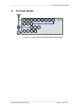
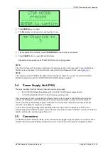
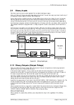
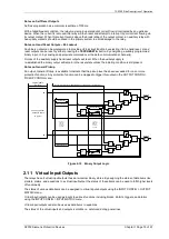
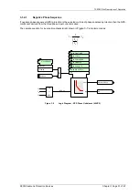
2.9 Binary Inputs
The binary inputs are opto-couplers operated from a suitably rated power supply.
Relays are fitted with 6 binary inputs (BI) depending on the variant. The user can assign any binary input to any of
the available functions (INPUT CONFIG > INPUT MATRIX).
Pick-up (PU) and Drop-off (DO) time delays are associated with each binary input. Where no pick-up time delay
has been applied the input may pick up due to induced AC voltage on the wiring connections (e.g. cross site
wiring). The default pick-up time of 20 ms provides AC immunity. Each input can be programmed independently.
Each input may be logically inverted to facilitate integration of the relay within the user scheme. When inverted the
relay indicates that the BI is energised when no voltage is applied. Inversion occurs before the PU and DO time
delay.
Each input may be mapped to any front Fascia indication LED and/or to any Binary output contact and can also
be used with the internal user programmable logic. This allows the relay to provide panel indications and alarms.
Each binary input is set by default to be read when the relay is in both the local or remote condition. A setting is
provided to allow the user to select if each individual input shall be read when the relay is in the local or remote
condition in the INPUT CONFIG > BINARY INPUT CONFIG menu.
Event
BI 1
Binary Input 1
=1
Inverted Inputs
BI 1 inverted
BI 1 P/U Delay
Event
BI
n
Binary Input
n
=1
BI
n
inverted
BI
n
P/U Delay
INPUT CONFIG>
INPUT MATRIX
(Or gates)
Logic signals,
e.g. '51-1 Inhibit'
BI 1 D/O Delay
BI
n
D/O Delay
INPUT
CONFIG>
BINARY
INPUT
CONFIG
Figure 2-9 Binary Input Logic
2.10 Binary Outputs (Output Relays)
Relays are fitted with 6 binary outputs (BO). All outputs are fully user configurable and can be programmed to
operate from any or all of the available functions.
In the default mode of operation, binary outputs are self reset and remain energised for a user configurable
minimum time of up to 60 s. If required, the outputs can be programmed to operate as ‘hand reset’ or ‘pulsed’. If
the output is programmed to be ‘hand reset’ and ‘pulsed’ then the output will be ‘hand reset’ only.
The binary outputs can be used to operate the trip coils of the circuit breaker directly where the trip coil current
does not exceed the 'make and carry' contact rating. The circuit breaker auxiliary contacts or other in-series
auxiliary device must be used to break the trip coil current.
Any BO can be assigned as a ‘Trip Contact’ in the OUTPUT CONFIG > TRIP CONFIG menu. Operation of a ‘Trip
Contact’ will operate any LED or virtual assigned from the 'Trip Triggered feature in the same menu and will
initiate the fault record storage, actuate the ‘Trip Alert’ screen where enabled and CB Fail protection when
enabled.
Where a protection function is mapped to an output contact, the output contact can be configured to trigger when
the protection function picks-up rather than when it operates. Such output contacts are configured via the
OUTPUT CONFIG > BINARY OUTPUT CONFIG > Pickup Outputs setting.
Notes on Pulsed Outputs
When operated, the output will reset after a user configurable time of up to 60 s regardless of the initiating
condition.
Summary of Contents for 7SR105 Rho
Page 1: ...Answers for energy 7SR105 Rho User Manual Motor Protection Relay Reyrolle Protection Devices ...
Page 2: ...Siemens Protection Devices 2 ...
Page 95: ...7SR105 Rho Technical Manual Chapter 4 Page 2 of 70 2018 Siemens Protection Devices ...
Page 99: ...7SR105 Rho Technical Manual Chapter 4 Page 6 of 70 2018 Siemens Protection Devices ...
Page 127: ...7SR105 Rho Technical Manual Chapter 4 Page 34 of 70 2018 Siemens Protection Devices ...
Page 153: ...7SR105 Rho Technical Manual Chapter 4 Page 60 of 70 2018 Siemens Protection Devices ...
Page 155: ...7SR105 Rho Technical Manual Chapter 4 Page 62 of 70 2018 Siemens Protection Devices ...
Page 157: ...7SR105 Rho Technical Manual Chapter 4 Page 64 of 70 2018 Siemens Protection Devices ...