7SR105 Rho Description of Operation
©2018 Siemens Protection Devices Chapter 1 Page 10 of 57
Section 2: Hardware Description
2.1 General
The structure of the relay is based upon the compact hardware platform. The relays are supplied in a Size 4 case.
The hardware design provides a commonality between the products and components across the range of relays.
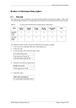
Table 2-1
Summary of 7SR105 Rho Motor Protection Relay Configurations
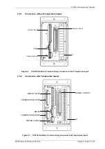
The 7SR105 Rho Motor Protection Relays are assembled from the following modules:
1. Front Fascia with 9 configurable LEDs and 1 Relay Healthy LED
2. Processor module
3. Current Analogue, Input module and Output module
4 x Current (Terminal X5)
6 x Binary Input (Terminal X1)
6 x Binary Outputs (Terminal X4)
4. Communication and Power Supply module
RS485 (Terminal X2)
Power supply (Terminal X3)
5. Temperature Inputs
With control push buttons
6 x Temp Inputs (Terminal X6 and X7)
Relay
Current
Inputs
Voltage
Inputs
Binary
Inputs
Binary
Outputs
Temperature
Inputs
LEDs
7SR1053-
XXXX-
2EA0
4
0
6
6
0
10
7SR1053-
XXXX-
2FA0
4
0
6
6
6
10
Summary of Contents for 7SR105 Rho
Page 1: ...Answers for energy 7SR105 Rho User Manual Motor Protection Relay Reyrolle Protection Devices ...
Page 2: ...Siemens Protection Devices 2 ...
Page 95: ...7SR105 Rho Technical Manual Chapter 4 Page 2 of 70 2018 Siemens Protection Devices ...
Page 99: ...7SR105 Rho Technical Manual Chapter 4 Page 6 of 70 2018 Siemens Protection Devices ...
Page 127: ...7SR105 Rho Technical Manual Chapter 4 Page 34 of 70 2018 Siemens Protection Devices ...
Page 153: ...7SR105 Rho Technical Manual Chapter 4 Page 60 of 70 2018 Siemens Protection Devices ...
Page 155: ...7SR105 Rho Technical Manual Chapter 4 Page 62 of 70 2018 Siemens Protection Devices ...
Page 157: ...7SR105 Rho Technical Manual Chapter 4 Page 64 of 70 2018 Siemens Protection Devices ...

