


Chapter 4 - 7SR105 Rho · Data Communications Definitions
© 2018 Siemens Protection Devices
Chapter 4 - Page 49 of 70
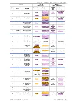
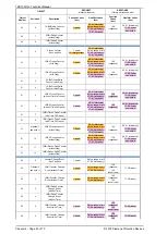
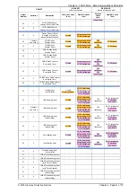
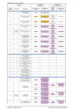
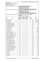
The following table lists both the Binary Output Status Points (Object 10) and the Control Relay Output Blocks (Object
12).
While Binary Output Status Points are included here for completeness, they are not often polled by DNP 3.0 Masters.
Binary Output Status points are not recommended to be included in class 0 polls.
As an alternative, it is recommended that “actual” status values of Control Relay Output Block points be looped
around and mapped as Binary Inputs. (The “actual” status value, as opposed to the “commanded” status value, is the
value of the actuated control. For example, a DNP control command may be blocked through hardware or software
mechanisms; in this case, the actual status value would indicate the control failed because of the blocking. Looping
Control Relay Output Block actual status values as Binary Inputs has several advantages:
•
it allows actual statuses to be included in class 0 polls,
•
it allows change event reporting of the actual statuses, which is a more efficient and
time-accurate method of communicating control values,
•
and it allows reporting of time-based information associated with controls, including any
delays before controls are actuated, and any durations if the controls are pulsed.
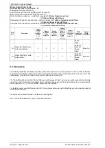
The default select/control buffer size is large enough to hold 10 of the largest select requests possible.
Binary outputs are by default NOT returned in a class zero interrogation.
Note, not all points listed here apply to all builds of devices.
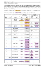
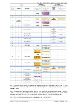
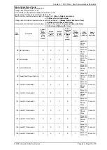
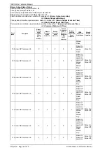
Binary Output Status Points
Static (Steady-State) Object Number: 10
Change Event Object Number: 11
Control Relay Output Blocks (CROB) Object Number: 12
Binary Output Command Event Object Number: 13
Static Variation reported when variation 0 requested: 1 (Binary Output w/o status)
or 2 (Binary Output with status)
Change Event Variation reported when variation 0 requested: 1 (Binary Output Event w/o Time)
or 2 (Binary Output Event with Time)
Command Event Variation reported when variation 0 requested: 1 (Command Status w/o Time)
or 2 (Command Status with Time)
Point
Index
Description
Default
Change
Event
Assigned
Class
(1, 2, 3
or none)
Default
Variation
Static
Object 10
Default
Variation
Event
Object 11
Default
Command
Event
Object 13
Assigned
Class
(1, 2, 3
or none)
Default
Variation
Command
Event
Object 13
CROB
Supported
Operations
Default
CROB
Operations
1 RL 1
0
2
2
0
1
Pulse On
Latch On
Paired
Close
Pulse On
2 RL 2
0
2
2
0
1
Pulse On
Latch On
Paired
Close
Pulse On
3 RL 3
0
2
2
0
1
Pulse On
Latch On
Paired
Close
Pulse On
4 RL 4
0
2
2
0
1
Pulse On
Latch On
Paired
Close
Pulse On
5 RL 5
0
2
2
0
1
Pulse On
Latch On
Paired
Close
Pulse On
6 RL 6
0
2
2
0
1
Pulse On
Pulse On
Summary of Contents for 7SR105 Rho
Page 1: ...Answers for energy 7SR105 Rho User Manual Motor Protection Relay Reyrolle Protection Devices ...
Page 2: ...Siemens Protection Devices 2 ...
Page 95: ...7SR105 Rho Technical Manual Chapter 4 Page 2 of 70 2018 Siemens Protection Devices ...
Page 99: ...7SR105 Rho Technical Manual Chapter 4 Page 6 of 70 2018 Siemens Protection Devices ...
Page 127: ...7SR105 Rho Technical Manual Chapter 4 Page 34 of 70 2018 Siemens Protection Devices ...
Page 153: ...7SR105 Rho Technical Manual Chapter 4 Page 60 of 70 2018 Siemens Protection Devices ...
Page 155: ...7SR105 Rho Technical Manual Chapter 4 Page 62 of 70 2018 Siemens Protection Devices ...
Page 157: ...7SR105 Rho Technical Manual Chapter 4 Page 64 of 70 2018 Siemens Protection Devices ...