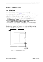


7SR105 Rho and 7SR17 Rho Applications Guide
©2018 Siemens Protection Devices
Chapter 7 Page 7 of 31
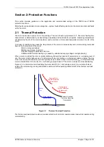
Gn 49 NPS Weighting
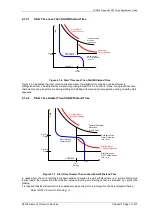
Where ‘Average’ is selected the relay uses the average 3-phase RMS current in the thermal algorithm, this is
suitable for static plant e.g. thermal protection of a cable.
Negative phase sequence current has an increased heating effect on rotating plant e.g. a motor. The relay should
be set to ‘Sequence Components’ when applied to a motor.
Gn 49 NPS Weighting Factor (K)
The NPS component weighting factor value (K) should be in line with manufacturers data where provided. Where
this data is not available it is recommended that the default value (K = 3) is used.
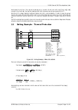
Gn 49 Thermal Overload
The thermal overload setting takes into account both the motor full load current and the CT ratio.
Typically ‘Itheta thermal Overload’ setting = 1.05 x motor rated current.
If it known that the rating of the motor is well in excess of the requirements of the drive the normal motor load
current will be less than the motor rated current. A thermal overload setting can be chosen to protect the drive and
over protect the motor.
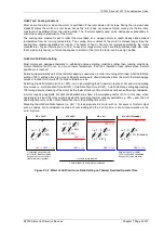
Gn 49 Motor Start Type
Selected to ‘%Itheta’ where the motor start current is above it’s running current.
For a VFD the start current may not be appreciably higher than the running current a binary input programmed to
‘Start Motor I/P’ can be used, see below. Note that a motor running condition is recognised by the relay when
current increases from the ‘motor stopped’ level to a ‘NOT motor stopped level’.
‘Start Motor I/P’ triggers a Data Report File and initialises the start prtotection
Gn 49 Motor Start Current
The motor starting current is usually taken to be the same as the locked rotor current. The Motor Start Current
setting should be less than this value and above the full load running current. The default value is 1.5 x Itheta (I
θ
).
The starting current of a VFD motor may not be appreciably higher than the running current, a Motor Start Current
setting cannot be applied. When the motor runs up to speed the heating time constant will be applied (rather than
the starting time constant).
End of Start Type
Can be either by measured current (%Itheta) or for VFD motors a binary input programmed to ‘Motor Running I/P’
can be used.
The default setting (% Itheta) requires no wiring to a relay BI.
Gn49 End of Start
The end of the start can be defined when the current returns to below the thermal overload setting. The default
Gn 49 End of Start setting is 1.05 x Itheta (I
θ
).
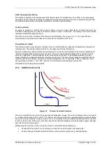
Gn 49 Motor Stop Type
This can be determined from current level (%Itheta), from current level checked by a binary input programmed to
‘CB Open’ condition or from current level checked by a binary input programmed to ‘No Accel’.
The default setting (% Itheta) requires no wiring to a relay BI.
Gn 49 Motor Stop Current
This is set at a value of current below which the motor is considered to be stopped. Typically a setting of 0.1 x Iθ
is used.
Summary of Contents for 7SR105 Rho
Page 1: ...Answers for energy 7SR105 Rho User Manual Motor Protection Relay Reyrolle Protection Devices ...
Page 2: ...Siemens Protection Devices 2 ...
Page 95: ...7SR105 Rho Technical Manual Chapter 4 Page 2 of 70 2018 Siemens Protection Devices ...
Page 99: ...7SR105 Rho Technical Manual Chapter 4 Page 6 of 70 2018 Siemens Protection Devices ...
Page 127: ...7SR105 Rho Technical Manual Chapter 4 Page 34 of 70 2018 Siemens Protection Devices ...
Page 153: ...7SR105 Rho Technical Manual Chapter 4 Page 60 of 70 2018 Siemens Protection Devices ...
Page 155: ...7SR105 Rho Technical Manual Chapter 4 Page 62 of 70 2018 Siemens Protection Devices ...
Page 157: ...7SR105 Rho Technical Manual Chapter 4 Page 64 of 70 2018 Siemens Protection Devices ...