Appendix
A.3 Site Setup For SITRANS F
FUP1010 IP67 Portable
Operating Instructions, 03/2012, A5E02951522-02
145
A.3
Site Setup For SITRANS F
How to use the Windows HyperTerminal Program
Windows provides a communication program called HyperTerminal, which is ideal for
interfacing your computer with the flow meter. The following typical example explains how to
set up HyperTerminal.
Note
Depending upon the Windows applications being used this setup procedure may vary.
1.
From the Windows desktop, left-click on the [START] button.
2.
Holding down the left mouse button, move the highlight up to [Programs], then across to
[Accessories] then [Communications]. Slide the highlight down to [HyperTerminal], then
release the left mouse button.
3.
Within the HyperTerminal window, move the mouse pointer down to [Hyperterm.exe] and
then double-click the left mouse button.
4.
This selects the [Connection Description] dialog box. Enter a name for your connection
(e.g., 1010N). You can optionally select an icon for this connection by clicking on one of
the icons displayed in the scrolling frame at the bottom of the window. Click [OK].
5.
This selects the [Phone Number] dialog box. Move the cursor to the arrow at the right of
the [Connect Using] field. Left click on the arrow to expand the field and then move the
highlight down to [Direct to Com 1 (or 2)] depending on the port connected to the
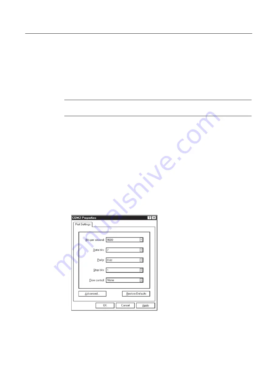
interface cable. Click [OK] to select the [Com 1 (or 2) Properties] Dialog box. Set up your
RS-232 parameters as shown in the example below. Left-click on the [OK] button.
6.
You will now see a blank terminal screen. Next left-click [File] on the top menu bar. Drag
the highlight down to [Properties] and then left-click.
Summary of Contents for 7ME3510
Page 2: ......
Page 10: ...Table of contents FUP1010 IP67 Portable 8 Operating Instructions 03 2012 A5E02951522 02 ...
Page 159: ...1010WP 7 21614 C ...
Page 160: ...1010WP 7 21614 C ...
Page 161: ...1010WDP 7 21614 C ...
Page 162: ...1010WDP 7 21614 C ...
Page 163: ......
Page 164: ......
Page 165: ......
Page 167: ...1012FP 8 DIRECT MODE REFLECT MODE INSTALLED ON PIPE 21614 C ...
Page 168: ......
Page 169: ...21614 C ...
Page 170: ......
Page 171: ......
Page 172: ......
Page 173: ......
Page 174: ...21614 C ...
Page 175: ...21614 C ...
Page 176: ...21614 C ...
Page 177: ...21614 C ...
Page 178: ...21614 C ...
Page 179: ...21614 C ...
Page 180: ...21614 C ...
Page 181: ......
Page 182: ......
Page 183: ...21614 C ...
Page 184: ...21614 C ...
Page 185: ...1012TP S 8 OUTLINE DIMENSIONS REFLECT MODE DIRECT MODE 1012TP S SERIES 21614 C MOUNTING TRACK ...
Page 186: ...REFLECT MODE DIRECT MODE 21614 C ...
Page 187: ...1015BC 1 8 21614 C ...
Page 188: ...21614 C INPUT OUTPUT TERMINALS 1015WP T10 8 ...
Page 189: ...21614 C INPUT OUTPUT TERMINALS 1015WP T26 8 ...
Page 190: ......
Page 191: ......
Page 192: ......
Page 193: ......
Page 195: ...DUAL HEAD CONFIGURATION 21614 C IN LINE CONFIGURATION FLOW ...
Page 196: ......
Page 197: ......
Page 208: ...Glossary FUP1010 IP67 Portable 162 Operating Instructions 03 2012 A5E02951522 02 ...
Page 212: ...Index FUP1010 IP67 Portable 166 Operating Instructions 03 2012 A5E02951522 02 ...
Page 213: ......


