


Troubleshooting
10.3 Test Facilities Graph Screen
FUP1010 IP67 Portable
Operating Instructions, 03/2012, A5E02951522-02
127
)
96
>@
'
7Q
G7
6
61
0LQ'DPS
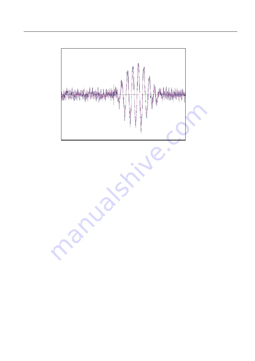
Figure 10-1 Test Facilities Graph Screen
Entering the Diagnostic Graph Screen
Before you can view the Diagnostic Graph Screen the flow channel must first be properly
installed and operating in a non-empty condition. If a previously installed channel is in a
"Fault" condition, but not reporting "Empty", you can still access the Graph Screen to aid in
troubleshooting the cause of the failure to measure flow.
To view the Graph Screen first enter the [Test Facilities] menu, which is a submenu of the
main [Diagnostic Data] menu.
1.
Pressing the <Up/Down Arrows>, scroll to the [Graph] menu item.
2.
Press the <Right Arrow> to enter the [Graph] menu and scroll to highlight the [Yes] item
in the option list.
3.
Now press the <ENTER> key to access the Graph Screen.
4.
To exit the Graph Screen and return to the main menu, press the <MENU> key once.
Diagnostic Text Display
The text to the upper left-hand corner of the screen represents diagnostic items which can
be individually turned on or off to reduce unnecessary clutter on the screen. This text display
can be modified by pressing the <ENTER> key and scrolling up or down through the various
parameters that appear in the Graph Display menu. Pressing the <ENTER> key will select
the highlighted parameter (a "+" sign appears next to selected items) and pressing <CLR>
will deselect the item. Pressing the <Left Arrow> will return you to the graph screen with the
selected parameters appearing at the top left corner of the screen. (The sample graph above
is shown with all diagnostics items selected).
Summary of Contents for 7ME3510
Page 2: ......
Page 10: ...Table of contents FUP1010 IP67 Portable 8 Operating Instructions 03 2012 A5E02951522 02 ...
Page 159: ...1010WP 7 21614 C ...
Page 160: ...1010WP 7 21614 C ...
Page 161: ...1010WDP 7 21614 C ...
Page 162: ...1010WDP 7 21614 C ...
Page 163: ......
Page 164: ......
Page 165: ......
Page 167: ...1012FP 8 DIRECT MODE REFLECT MODE INSTALLED ON PIPE 21614 C ...
Page 168: ......
Page 169: ...21614 C ...
Page 170: ......
Page 171: ......
Page 172: ......
Page 173: ......
Page 174: ...21614 C ...
Page 175: ...21614 C ...
Page 176: ...21614 C ...
Page 177: ...21614 C ...
Page 178: ...21614 C ...
Page 179: ...21614 C ...
Page 180: ...21614 C ...
Page 181: ......
Page 182: ......
Page 183: ...21614 C ...
Page 184: ...21614 C ...
Page 185: ...1012TP S 8 OUTLINE DIMENSIONS REFLECT MODE DIRECT MODE 1012TP S SERIES 21614 C MOUNTING TRACK ...
Page 186: ...REFLECT MODE DIRECT MODE 21614 C ...
Page 187: ...1015BC 1 8 21614 C ...
Page 188: ...21614 C INPUT OUTPUT TERMINALS 1015WP T10 8 ...
Page 189: ...21614 C INPUT OUTPUT TERMINALS 1015WP T26 8 ...
Page 190: ......
Page 191: ......
Page 192: ......
Page 193: ......
Page 195: ...DUAL HEAD CONFIGURATION 21614 C IN LINE CONFIGURATION FLOW ...
Page 196: ......
Page 197: ......
Page 208: ...Glossary FUP1010 IP67 Portable 162 Operating Instructions 03 2012 A5E02951522 02 ...
Page 212: ...Index FUP1010 IP67 Portable 166 Operating Instructions 03 2012 A5E02951522 02 ...
Page 213: ......