l
F.8L Falco Construction Manual
27–13
Revision 4, March 1, 2002
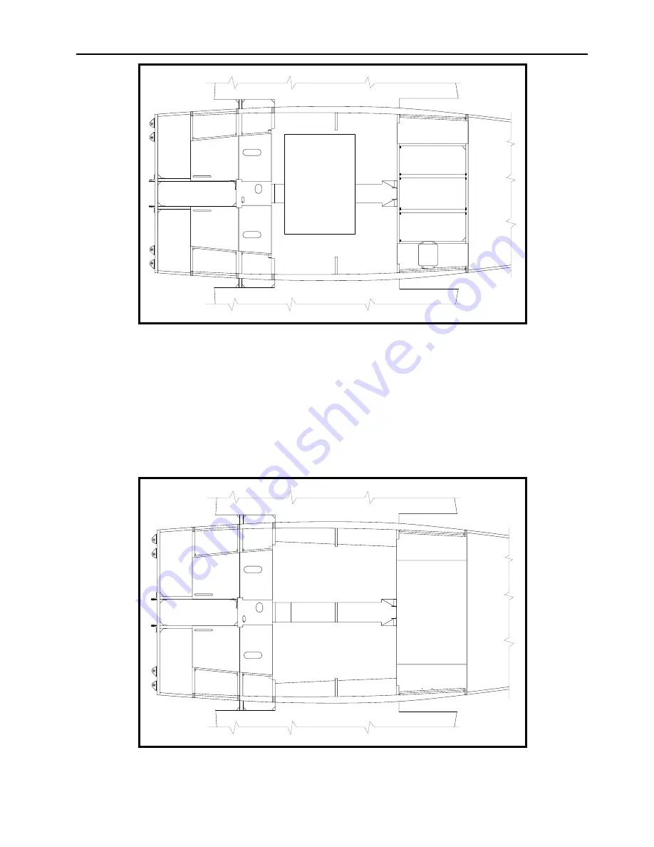
Figure 23
❏
Remove the center luggage compartment floor and position the strobe power supply as
shown in Figure 23. (The power supply will be installed on the underside of the floor, but
it’s easier to locate the holes this way.) The two inboard holes should be located just
inboard of the plywood floor, so that the screw heads will be hidden under the removable
center luggage compartment floor. The outboard holes should be located just inboard of
the cockpit side walls so that you will always be able to get to the mounting screws with a
screwdriver by lifting up the edge of the carpet. Drill the four 3/16” holes and set the
power supply aside.
Figure 24
Summary of Contents for F.8L Falco
Page 1: ...F 8L Falco Construction Manual...
Page 7: ...l F 8L Falco Construction Manual Revision 4 March 1 2002...
Page 21: ...l F 8L Falco Construction Manual 1 8 Revision 4 March 1 2002...
Page 29: ...l F 8L Falco Construction Manual 2 8 Revision 4 March 1 2002...
Page 43: ...l F 8L Falco Construction Manual 5 4 Revision 4 March 1 2002...
Page 65: ...l F 8L Falco Construction Manual 9 6 Revision 4 March 1 2002...
Page 81: ...l F 8L Falco Construction Manual 10 16 Revision 4 March 1 2002...
Page 109: ...l F 8L Falco Construction Manual 15 4 Revision 4 March 1 2002...
Page 133: ...l F 8L Falco Construction Manual 17 10 Revision 4 March 1 2002...
Page 145: ...l F 8L Falco Construction Manual 18 12 Revision 4 March 1 2002...
Page 173: ...l F 8L Falco Construction Manual 21 10 Revision 4 March 1 2002...
Page 229: ...l F 8L Falco Construction Manual 23 40 Revision 4 March 1 2002...
Page 387: ...l F 8L Falco Construction Manual 28 26 Revision 4 March 1 2002...
Page 393: ...l F 8L Falco Construction Manual A 6 Revision 4 March 1 2002...


