l
F.8L Falco Construction Manual
22–5
Revision 4, March 1, 2002
280
1100
Aileron Upper Trailing Edge Skin
Sta. 10-14
300
1100
Flap Upper Trailing Edge Skin
Sta. 2-6
300
1100
Flap Upper Trailing Edge Skin
Sta. 2-6
300
1100
Aileron/Flap Upper Trailing Edge Skin
Sta. 6-10
300
1100
Aileron/Flap Upper Trailing Edge Skin
Sta. 6-10
300
1100
Flap Lower Trailing Edge Skin
Sta. 2-6
300
1100
Flap Lower Trailing Edge Skin
Sta. 2-6
300
1100
Aileron/Flap Lower Trailing Edge Skin
Sta. 6-10
300
1100
Aileron/Flap Lower Trailing Edge Skin
Sta. 6-10
280
1100
Aileron Lower Trailing Edge Skin
Sta. 10-14
280
1100
Aileron Upper Trailing Edge Skin
Sta. 10-14
280
1100
Aileron Lower Trailing Edge Skin, Sta
10-14
Grain Direction
Grain Direction
Grain Direction
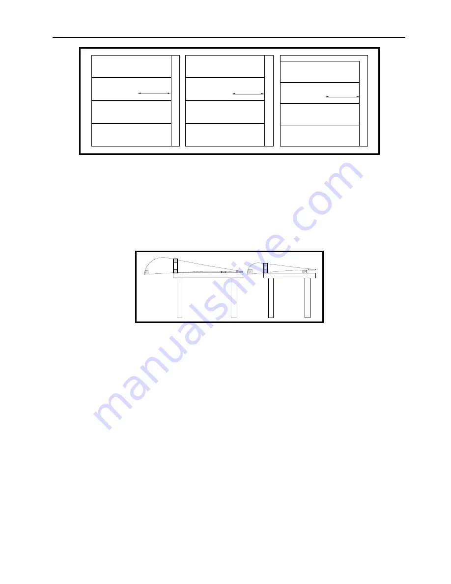
Figure 3
❏
Use three 48”x48” or larger sheets of 1mm birch plywood and cut in accordance with
Figure 3.
The aileron and flap are assembled as a single unit and will remain as a single unit until after the
wing is assembled. The trailing edge of the aileron/flap assembly will include enough extra length
for the wing. This will simplify the alignment of the trailing edge and insure that the wing,
aileron and flap will be aligned.
Figure 4
The aileron/flap assembly will require a number of simple jigs. As shown in Figure 4, the
aileron/flap spar will be placed on the edge of a flat table—this will allow the leading edge ribs to
clear the table. The aileron/flap spar is clamped in place so that it is exactly perpendicular to the
jig table. The trailing edge ribs are installed on the aft face of the spar. To assure proper
alignment, a long notched strip of wood is used to support the trailing edge ribs at the 95% chord
station. Figure 4 shows a section through Station 2 and Station 14, as do most of the other
illustrations in this chapter.
At the 95% chord station, the ribs are 253.5mm between stations when measured on the
diagonal. The thickness of the notched strip of wood is the difference between the altitude of the
bottom of the spar and the altitude of the bottom of the rib. (The bottom of the aileron/flap spar
is calculated from 69.0 at station 1—a theoretical point—and 71.0 at station 14.)
Summary of Contents for F.8L Falco
Page 1: ...F 8L Falco Construction Manual...
Page 7: ...l F 8L Falco Construction Manual Revision 4 March 1 2002...
Page 21: ...l F 8L Falco Construction Manual 1 8 Revision 4 March 1 2002...
Page 29: ...l F 8L Falco Construction Manual 2 8 Revision 4 March 1 2002...
Page 43: ...l F 8L Falco Construction Manual 5 4 Revision 4 March 1 2002...
Page 65: ...l F 8L Falco Construction Manual 9 6 Revision 4 March 1 2002...
Page 81: ...l F 8L Falco Construction Manual 10 16 Revision 4 March 1 2002...
Page 109: ...l F 8L Falco Construction Manual 15 4 Revision 4 March 1 2002...
Page 133: ...l F 8L Falco Construction Manual 17 10 Revision 4 March 1 2002...
Page 145: ...l F 8L Falco Construction Manual 18 12 Revision 4 March 1 2002...
Page 173: ...l F 8L Falco Construction Manual 21 10 Revision 4 March 1 2002...
Page 229: ...l F 8L Falco Construction Manual 23 40 Revision 4 March 1 2002...
Page 387: ...l F 8L Falco Construction Manual 28 26 Revision 4 March 1 2002...
Page 393: ...l F 8L Falco Construction Manual A 6 Revision 4 March 1 2002...


