


Locating the features and zone boundaries
FiberPatrol FP1150 Product Guide
Page 91
Zone boundary and site feature identification (fences)
The following figures illustrate the types of features that should be identified and located on the
FiberPatrol map. To accurately locate and display alarms on a scale site map, the FiberPatrol
software requires the locations of the start point of sensing cable; the end point of sensing cable;
all zone boundaries (beginning and end of each zone); service loops; sensitivity loops; isolation
loops (anywhere that extra cable is attached to the fence) corners and perimeter direction
changes; sensor cable bypasses; gates; buildings, structures and other obstacles that are located
on the perimeter.
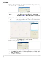
At the start point of sensing cable
At the start point of the sensing cable, tap the cable 10 m away from the start point post and
subtract 20 m to confirm the start point location.
Note
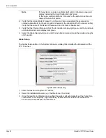
The FiberPatrol system uses “soft” zone boundaries, which are defined in
software. The location resolution of FiberPatrol is 4 m (13 ft.). Therefore,
if CCTV coverage will be used for alarm assessment there should be an
overlapping field of view of at least 8 m (26 ft.) at all zone boundaries (see
).
Figure 97 Overlapping CCTV visual assessment
Figure 98 Tap test location - sensor start point
8 m overlap (4 m/side minimum)
software defined zone boundary
perimeter fence
camera field of view
CCTV camera
tap cable 10 m away
service
loop (10 m)
from start point post
10 m (33 ft.)


