


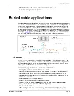


Buried cable applications
FiberPatrol FP1150 Product Guide
Page 43
•
calculate the required length of sensor cable and determine which FP1150 Series model best
suits the application; total cable length includes service loops, lead cable greater than 500 m,
plus approximately 5% overage of the cable length for installation variations, e.g., to protect a
140 km pipeline or perimeter, the head end equipment averages 150 m from the pipeline:
1.
Estimate cable requirement:
(2 X 80 km = 160 km) and (160 km - 140 km = 20 km) therefore, two FP115040 sensors
would be sufficient to cover the 140 km.
2.
Calculate cable requirement:
pipeline length = 140 km
distance between head end and pipeline requires 150 m lead cable X 4 = 600 m
cable splices (10 m X 8 splices = 80 m per cable, 80 m X 4 cables = 320 m)
5% overage 0.05 X (140 km + 0.6 km + 0.32 km) = 7.046 km
cable requirement (140 km + 0.6 km + 0.32 km + 7.046 km = 147.996 km rounded up to
148 km)
3.
Determine required models:
(160 km - 148 km = 12 km) therefore two FP115040 sensors provide sufficient cable
length coverage to protect a 140 km pipeline or perimeter
Cable installation for pipeline TPI detection
The recommended cable installation for third party interference places the sensor cable 30 cm
(1 ft.) centered above the protected pipeline. However, for installations where it would be difficult or
impractical to install the cable above the pipeline, the cable can be installed beside the pipeline.
For pipelines that have an existing run of fiber optic cable beside them, the cable can often be
retrofitted for the FiberPatrol sensor.
Cable installation for intrusion detection (above ground)
The recommended cable installation for above ground intrusion detection of human targets and
vehicles requires a cable burial depth of between 15 and 70 cm (6 and 28 in.) below ground level.
There are a number of factors to consider including the burial media along the cable path,
moisture content of the soil, and ground frost in the winter. The burial depth should be consistent
for the full length of the sensor cable.
Feature
Description
(length unit = meters, single pass coverage)
Cable length
lead cable
length of cable from equipment room to start of perimeter
length of coverage
length of required protection including any cable bypasses
service loops
at each splice location, and at the sensor unit, each section of
sensor cable requires a 10 m service loop (total number of
service loops) X 10 m
cable overage
calculated length of cable (above 3 features) X .05 (5%
overage for installation variations)
cable requirement
sum of the above 4 features = total cable requirement
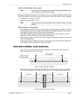
Figure 50 Example length calculation drawing
150 m
150 m
35 km
FP115040 control equipment (X 2)
140 km
35 km
35 km
35 km


