


FiberPatrol configurations
Page 22
FiberPatrol FP1150 Product Guide
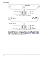
Line configurations
The line configuration is typically used when the sensor unit equipment is located at one end of the
protected perimeter, and the perimeter extends away from the equipment room in one direction.
The line configuration does not provide single cut redundancy. In the event of a cut or severely
damaged sensor cable, detection will continue between the start of the detecting sensor cable and
the cut/damaged point in the cable.
illustrate the line configuration.
If necessary, the non-detecting lead cable can be spliced to the detecting cable at the start point of
the sensor cable. Splices may also be required for other site specific features.
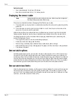
Figure 18 Recommended line configuration
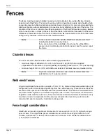
Figure 19 line configuration with start point splice
fiber optic cable (sensor cable/lead cable)
S1 (sensor fiber 1 - internal to fiber optic cable)
S2 (sensor fiber 2 - internal to fiber optic cable)
fusion splice
fiber optic termination
splice enclosure
sensor unit
non-detecting lead cable
Cable length = a + b
detection start point
indicates software defined start of detection
dual end module
fiber connection module
keyboard, monitor, mouse
fiber optic cable (sensor cable/lead cable)
S1 (sensor fiber 1 - internal to fiber optic cable)
S2 (sensor fiber 2 - internal to fiber optic cable)
fusion splice
fiber optic termination
splice enclosure
splice enclosure
sensor unit
Note: Cable length = a + b
detection start point
fiber connection module
keyboard, monitor, mouse


