


Buried cable applications
FiberPatrol FP1150 Product Guide
Page 41
Sensor cable terminations
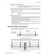
Each sensor fiber must be spliced to an end module to terminate the detecting sensor cable at the
ends of S1 and S2. At the end point, the sensor cable requires a 10 m (33 ft.) service loop to
provide access to the sensor cable and splice enclosure. The fusion splices at the fiber connection
module and end module are made after the sensor cable has passed the OTDR measurement
tests from both ends of the cable.
Figure 46
shows the recommended installation of an end
module.
Figure 47
shows the recommended installation of two end modules for contiguous
FiberPatrol sensors. In the example for the contiguous sensors, a short length of sensor cable is
used to splice the dark fibers that are required from one sensor system to the next.
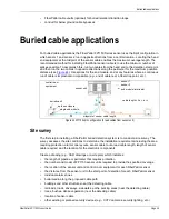
Figure 45 Example fiber drop point
Figure 46 Single end module installation
Figure 47 Back-to-back end module installation
splice enclosure
10 m service loop
buried vault
ground level
HDPE conduit
fiber optic cable (includes dark fiber)
sensor cable
sensor cable
10 m service loop
10 m service loop
splice enclosure
buried vault
ground level
sensor cable
10 m service loop
(includes end module)
splice enclosure
buried vault
ground level
sensor cable
10 m service loop
(includes end module)
cable used to splice
dark fibers (if required)
splice enclosure
10 m service loop
(includes end module)
sensor cable


