


Buried cable applications
FiberPatrol FP1150 Product Guide
Page 39
•
FiberPatrol cable vaults (optional) for buried isolation/transition loops
•
conduit for below ground cable bypasses
Buried cable applications
For buried cable applications the FiberPatrol FP1150 Series sensor uses the Split configuration in
which sensor 1 and sensor 2 run in opposite directions from a central location. Locating the head
end equipment at the midpoint of the sensor cable enables the maximum coverage length. The
recommended method for installing FiberPatrol sensor cable is to use the minimum number of
splices possible. To accomplish this, run two cables from the head end to the detection start point,
and then run the two cables in opposite directions along the perimeter for the maximum possible
distance (see
Figure 44
). Use splices for the end module, and at any features where a continuous
run of cable is impractical or impossible (e.g., end of cable reel, a fiber drop point, etc.).
Site survey
The first step in installing a FiberPatrol buried detection system is to conduct a site survey. The
survey assesses the site conditions to determine the installation requirements including the area
requiring protection, alarm zone layouts, sensor cable route, lead cable length, length of sensor
cable required, and the location for the electronic components.
Create a drawing (e.g., CAD drawings or a site plan) which indicates:
•
the length of pipeline or perimeter that requires protection
•
the number and model of FP1150 sensor units required to provide the specified coverage
•
the location of the sensor unit and control room equipment for each FiberPatrol sensor
•
the distance from the sensor unit to the start point of detection for each FiberPatrol sensor
•
individual alarm zones
•
burial media along the proposed cable path
•
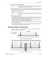
buildings and other structures near the detecting cable
•
railroads, roads, driveways, sidewalks, paths, parking areas (near the detecting cable)
•
trees, bushes, dense vegetation (near the detecting cable)
•
location of sensor cable
•
other existing or planned security devices (e.g., CCTV cameras, security lighting, etc.)
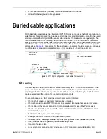
Figure 44 FP1150 split configuration (2 lead cables from sensor unit)
control room
equipment
cable length = 2a + b + c
splice enclosure
sensor 1
sensor 2
end module/terminator
buried vault
midpoint of sensor cable length
single end module
sensor unit


