


FiberPatrol Overview
Page 10
FiberPatrol FP1150 Product Guide
The FiberPatrol system includes Windows-based configuration and alarm display software, which
is used to setup and calibrate the system. The configuration software can also serve as an
operator interface to the system for alarm monitoring. The configuration software enables sensor
calibration, detection parameter adjustments, system configuration settings and alarm processing.
FiberPatrol can operate as a standalone sensor, which communicates alarm conditions via
optional relay output modules. A PC-based security management system, such as the Network
Manager’s Alarm Integration Module, or StarNet 2, can serve as the primary operator interface for
a FiberPatrol system. FiberPatrol can also report alarms to 3rd party security management
systems (SMS) via the Network Manager Service. The security management system monitors the
FiberPatrol sensor, and can report alarms to an operator on a graphic site-map.
FiberPatrol sensor system details
•
passive, fiber optic, outdoor perimeter intrusion detection system
•
uses standard outdoor-rated telecommunication grade single-mode fiber optic cable for fence
protection
•
uses armored telecommunication grade single-mode fiber optic cable that is suitable for direct
burial for buried applications
•
additional dark fibers available for auxiliary perimeter device communications
•
models available for single pass coverage for fences up to 4.3 m (14 ft.) high
•
no power required for outdoor components
•
outdoor components unaffected by lightning, EMI, or electrical transients
•
outdoor rated splice enclosures for fiber termination and access to fibers at drop points
•
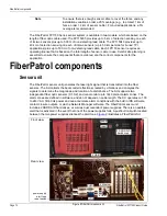
indoor components are rack-mountable in a standard EIA 19 in. equipment rack:
•
sensor unit - 4RU component transmits laser light into two dedicated fibers and receives
and isolates back-scatter signals via the integral start module, analyzes the received
signal, locates disturbances, triggers alarms, monitors system status, includes Windows
operating system, FiberPatrol system software, configuration software and Network
Manager software
•
fiber connection module - 1RU panel for connecting the 2 fiber sensors (S1 and S2) from
the sensor unit to the lead cable in the equipment room, includes one 12-splice tray for
making the required fusion splices and a dual end module; a second splice tray can be
added, if required
•
rack-mount LCD keyboard/monitor/mouse combo - 1 RU panel provides control,
maintenance, calibration and configuration access to the FiberPatrol processor
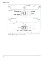
FP1150 configurations
There are three distinct configurations for the FP1150 Series sensor:
•
Loop configurations in which the two sensors run in opposite directions in one fiber optic
cable.
•
Split configurations in which the two sensors run in opposite directions, in two fiber optic
cables.
•
Line configurations in which both sensors run in the same direction in one fiber optic cable.
The loop configuration provides single cable cut immunity whereby detection will continue over the
full length of the perimeter in the event of a single cut in the sensor cable. In the split configuration,
the two sensors work independently to provide twice the linear length of protection as compared to
the loop configuration. However, a cut cable ends detection beyond the point of the cut. In the line
configuration, the two sensors run in the same direction in the sensor cable and work in tandem for
alarm detection. With the line configuration, a cut cable ends detection beyond the point of the cut.


