


Creating the site map
Page 100
FiberPatrol FP1150 Product Guide
2.
Start at the beginning of the sensing sensor cable, and add the start point vertex to the map.
3.
Proceed around the perimeter map and use the completed location/calibration table to place a
vertex at each located feature.
•
To remove a vertex, select the Perimeter Removal tool (hover the cursor over the vertex
and the hand becomes the removal tool) and left-click the vertex.
When a vertex is removed, the adjacent vertices are joined by a straight line.
•
To add a vertex inside an existing line segment, highlight the segment, and select the Split
Tool. This creates a vertex in the center of the highlighted segment. Left-click and drag this
vertex to the desired location.
•
To change the location of a vertex left click and release to select the vertex, then left click
and hold to drag the vertex to the desired location.
Figure 117 Drawing the perimeter
Note
To end the drawing sequence, select Ctrl + 3. The perimeter line ends at
the last vertex.
Note
Once the perimeter is drawn, a table is created based on the physical
location of each vertex. The physical (ground) distances must then be
changed to the optical distances that were obtained during the testing.
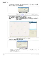
Figure 118 Defining the positions of the perimeter segments
Note
For line configurations, the last node can be left unconnected. For
closed loop configurations, the start and end nodes must be the same.
superimposed start point
and end point vertices
Perimeter segment definition table
select a segment
enter the Start point
and End point


