


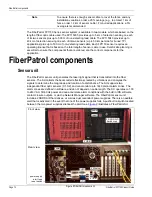


FiberPatrol configurations
FiberPatrol FP1150 Product Guide
Page 19
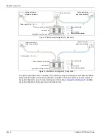
The partially closed loop configuration uses a dual end module in the fiber connection module in
the equipment rack. This configuration uses two lead cables and the two sensing fibers (S1 and
S2) run in opposite directions around the perimeter. The partially closed loop provides single cut
redundancy. In the event of a cut or severely damaged sensor cable, detection will continue
around the perimeter in both directions to the point of the damage.
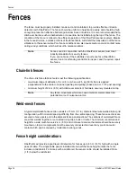
Split configuration
The split configuration provides extended length coverage by using each sensor fiber
independently. Buried cable applications typically use the Split configuration. To get the maximum
length coverage, the sensor unit is located near the mid-point. Two sensor cables run in opposite
directions along the perimeter with each end module located up to 40 km (25 mi.) away from the
sensor unit (up to 50 km {31 mi.} for TPI). One sensor fiber provides detection in each direction
with S1 running one way and S2 running the opposite way. A splice enclosure is required on the
fence at the start point to use one lead cable (see
). Using two lead cables eliminates the
requirement for a start point splice (see
).
Figure 13 FiberPatrol partially closed redundant loop configuration
FiberPatrol sensor cable
fiber optic cable (sensor cable/lead cable)
S1 (sensor fiber 1 - internal to fiber optic cable)
S2 (sensor fiber 2 - internal to fiber optic cable)
Note: Cable length = a + b + c + d + e + f + g
(min. possible required splices = 4)
fiber connection
module includes
dual end module
sensor unit
keyboard, monitor, mouse


