Installation manual of system “bp408” - Commissioning
107
NOTE!
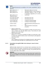
For regulated lift systems, the instruction of the inverter manufacturer must be
observed.
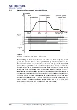
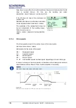
Braking distance V1...7
=
Deceleration distance to the floor
Braking distance VI
=
Deceleration distance in case of inspection
Braking distance VR
=
Deceleration distance in case of return
(If separately supported by the drive.)
Braking distance V0
=
Cut-off point
(Stopping distance)
Re-levelling downwards
=
Re-levelling to the floor
Re-levelling upwards
=
Re-levelling to the floor
Lower levelling area
=
Levelling test during stoppage
Upper levelling area
=
Levelling test during stoppage
Lower zone area
=
Starting point doors opening early to the
floor
Upper zone area
=
Starting point doors opening early
to the floor
Shaft pit (underpinning)
Default value is 1 m. This can be adjusted according to the actual value in
order to measure the shaft with effective values. It also defines the valid
application area of the encoder.
Shaft head (Headroom)
Shaft pit is 1.5 m. This can be adjusted according to the actual value in order
to measure the shaft with effective values. It also defines the valid application
area of the encoder.
Car height
This is required for the start-up of the maintenance position, which should be
chosen such that the assembler can comfortably get on the car ceiling.
8.11.5
Deceleration through S81/S82 in the end stops in case of normal
operation
Additional safety equipment for the end stops may be necessary due to the
structural condition of the system. It should ensure that the lift is safely switched to
the drive-in speed (V0) before reaching the end stops. This possibility offers the
use of the delay switches S81 and S82.
WARNING!
What is essential for the function of the correction switches S81 and S82 is that
they must be installed at the end stop at the right deceleration point and must
switch safely.
Summary of Contents for bp408
Page 2: ......
Page 24: ...24 Installation manual of system bp408 Safety instructions...
Page 52: ...52 Installation manual of system bp408 The control system bp408...
Page 58: ...58 Installation manual of system bp408 Installation and assembly...
Page 80: ...80 Installation manual of system bp408 Electrical connection...
Page 118: ...Installation manual of system bp408 Appendix 118 Appendix A Menu navigation bp408...
Page 119: ...119 Installation manual of system bp408 Appendix B Update of the firmware via USB stick...


