Installation manual of system “bp408” - Electrical connection
73
7.7.6
Node numbers of CAN components
Each CANopen Lift component has a node number (Node-ID) for identification. It
must be unique within a CANopen Lift network. If there are two components with
the same ID on the bus, these assmblies cannot be approached.
At Böhnke + Partner GmbH, the node numbers (Node-ID) are issued according to
the recommendation of the SIG-Lift Control (www.CANopen-Lift.org/wiki/Node-IDs)
according to the following scheme:
If you obtain the control system from Böhnke + Partner GmbH, all node numbers
(Node-IDs) are already set by default.
7.8
Flat travelling line to car terminal box
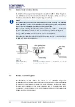
The cabin terminal box is connected via a H05VEA7VH6-F flat travelling line. The
assignment of the wires can be found in the circuit diagrams enclosed with the
control system.
Node-ID
[decimal]
CAN1
Local bus
CAN2
Shaft bus
1
bp408 - lift control system
bp408 – lift control system G1
2
Drive (frequency converter)
bp408 – lift control system G2
3
reserved
bp408 – lift control system G3
4
Transmitter/positioning 1
bp408 – lift control system G4
5
Transmitter/positioning 2
bp408 – lift control system G5
6
reserved
bp408 – lift control system G6
7
Door control system 1 (door A)
bp408 – lift control system G7
8
Door control system 2 (door B)
bp408 – lift control system G8
9
Door control system 3 (door C)
CDG-01 /CSI-01 – Bridge / Repeater
10
CDG-01 - Gateway / CSI-01 - Bridge
Bridge / Repeater 2
11
CIO-01 in control cabinet
Bridge / Repeater 3
12
Inspection box with CLK-03
Bridge / Repeater 4
13
Load measurement
Bridge / Repeater 5
14
Energy meter
Bridge / Repeater 6
15
reserved
Bridge / Repeater 7
16
CAP-02 / CBK-01 inner tableau node 1
Bridge / Repeater 8
17-20
CAP-02 / CBK-01 inner tableau nodes 2 - 5
21-84
CAP-02 / CBK-01 / CIO-01 in shaft
111-118
CAP-02 / CIO-01 in control cabinet
119
CWI-01
125
Default Node-ID (default setting of a bearing component such as wie CAP-02, CBK-01 or
CIO-01)
126
Flash update of bootloader
127
CANWizard
Summary of Contents for bp408
Page 2: ......
Page 24: ...24 Installation manual of system bp408 Safety instructions...
Page 52: ...52 Installation manual of system bp408 The control system bp408...
Page 58: ...58 Installation manual of system bp408 Installation and assembly...
Page 80: ...80 Installation manual of system bp408 Electrical connection...
Page 118: ...Installation manual of system bp408 Appendix 118 Appendix A Menu navigation bp408...
Page 119: ...119 Installation manual of system bp408 Appendix B Update of the firmware via USB stick...


