66
Installation manual of system “bp408” - Electrical connection
7.6
Electrical installation
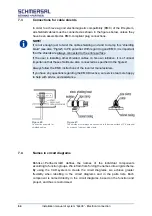
After mechanical assembly of all components, carry out the electrical installation
using the circuit diagrams provided. Ensure proper connection of all terminal points
and compliance with EMC wiring guidelines.
WARNING!
Cables and plugs may only be mounted or removed in a de-energised state.
7.7
Bus connections
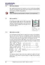
The bp408 control system uses the CAN bus according
to the application profile CiA 417. This profile also
describes the physical parameters of the bus lines and
the topology. Special regulations generally apply for the
wiring of bus systems.
7.7.1
Electrical bus medium
The components according to CiA 417 require a two-wire line for communication.
From the point of view of the bus, the individual connected components are
referred to as nodes. The nodes are connected in parallel to the bus. While doing
so, it must be ensured that the topology of the bus line always forms a line.
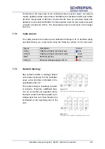
The CAN high-speed standard (ISO11898-2) requires that the bus be terminated
at the beginning and at the end with a resistor (120 ohms). Termination can be
done in different ways. For
some nodes, an internal
resistor can be activated via a
DIL switch or jumper, and for
others, a resistor must be
connected
to
the
bus
terminals.
For
exact
termination, refer to the
manuals of all connected
nodes!
The maximum number of nodes on the bus is limited to 64 nodes by the driver
blocks used. If more nodes are required, repeaters or bridges must be used (see
further below).
Figure 43:
Lift
components
that
comply
with
the
application profile CiA 417
must bear this logo.
Figure 44:
The bus must be terminated at the beginning and end with a
120 ohms resistor.
Summary of Contents for bp408
Page 2: ......
Page 24: ...24 Installation manual of system bp408 Safety instructions...
Page 52: ...52 Installation manual of system bp408 The control system bp408...
Page 58: ...58 Installation manual of system bp408 Installation and assembly...
Page 80: ...80 Installation manual of system bp408 Electrical connection...
Page 118: ...Installation manual of system bp408 Appendix 118 Appendix A Menu navigation bp408...
Page 119: ...119 Installation manual of system bp408 Appendix B Update of the firmware via USB stick...


