36
Installation manual of system “bp408” - The control system “bp408”
5.7.3
Control panel and LCD in bp408
With the help of the graphic LC display and the control panel, the state of the lift
can be determined and parameters in the control system and connected CANopen
lift devices changed.
5.7.3.1
Standard view
After the system is switched on and during normal mode,
if special menu is not called, the standard view is
displayed on the display. This view gives a quick overview
of the latest state of the lift and provides individually
configurable information.
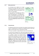
The following information is displayed on the LCD by
default:
lift status bar
safety circuit status bar
logo “B+P” (or customer-specific characters)
optionally also the board or cabinet temperature,
State of internal buffer battery
the current system time
and depending on the configuration:
current faults or messages
most recent fault
statistical information
current speed of lift
5.7.3.2
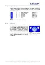
Lift status bar
The lift status bar is located in the top part of the display. It is displayed in all menus.
The following information is displayed in the lift status bar:
Pilot control (relay K1-K3)
doors A/B/C with limit switches and
door switching signals
(light barrier, key “door open”)
Mode (e.g. inspection mode)
Flush infor/ =/ -
Direction indicator
Floor position
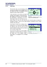
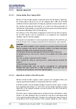
Figure 22:
The lift status bar is displayed in all menus
Figure 21:
Display and keys of bp408.
Here is a display of two doors A
and B.
Summary of Contents for bp408
Page 2: ......
Page 24: ...24 Installation manual of system bp408 Safety instructions...
Page 52: ...52 Installation manual of system bp408 The control system bp408...
Page 58: ...58 Installation manual of system bp408 Installation and assembly...
Page 80: ...80 Installation manual of system bp408 Electrical connection...
Page 118: ...Installation manual of system bp408 Appendix 118 Appendix A Menu navigation bp408...
Page 119: ...119 Installation manual of system bp408 Appendix B Update of the firmware via USB stick...


