background image


Installation manual of system “bp408” - Electrical connection 


71


7.7.4.4 

Two-part group with three lines 

 
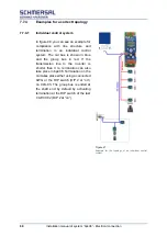
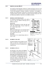
Figure 51 shows the bus topology of a two-part group with three lines for hall calls. 
Since a line structure can no longer be adhered to with more than two lines, bridges 
are  used  here.  Thus,  each  cable  in  turn  forms  an  independent  line.  The  bus  is 
terminated at each end. 


NOTE

Pay attention to the termination during commissioning. Usually only a single lift is 
put into operation and the group connection is established later. In this case, the 
termination must be adjusted (see individual control system). 


Figure 50:


Example of topology of a two-part group with three lines


Summary of Contents for bp408

Page 1: ...Installation manual System bp408 General instructions Safety instructions Commissioning EU Type Examination...

Page 2: ......

Page 3: ...slation presentation reproduction duplication by photocopying or in some other ways storage on electronic medium and modification as a whole or in parts are reserved for the publisher This manual does...

Page 4: ...rols 19 4 Standards 25 4 1 EMC Directive 25 4 2 EN 81 26 5 The control system bp408 27 5 1 Product and functional description 27 5 2 An overview of the functions of bp408 28 5 3 Decentralised lift con...

Page 5: ...tion 59 7 1 Preparations 59 7 2 Interference suppression measures and notes 60 7 3 Connections for cable shields 64 7 4 Names in circuit diagrams 64 7 5 Safety circuit 65 7 6 Electrical installation 6...

Page 6: ...the high drive speed 101 8 10 Sequence of a direct drive in with DCP 102 8 11 Setting up the copying tool 102 8 11 1 Installing the delay switch 103 8 11 2 Basic settings 104 8 11 3 Setting drive with...

Page 7: ...oducts as Manual To obtain a better overview the manual has been divided into several parts The Installation manual tells you about the hazards and risks which can result in serious health problems an...

Page 8: ...s permissible only with the consent of B hnke Partner GmbH and with precise reference to the source B hnke Partner logo and company name are protected trademarks The information in this manual is regu...

Page 9: ...safety equipment according to the standards of the safety technology First aid training 2 2 Safety instructions for control system ATTENTION Excerpts from chapter 5 of DGUV 209 053 Activities perform...

Page 10: ...car roof 5 5 2 Shaft lighting Before beginning work in the shaft sufficient lighting must be ensured e g switch on the shaft lights and carry along a network independent light 5 5 3 Stay and drives i...

Page 11: ...movements are forbidden at a certain time 5 6 Completion of activities After completion of activities all equipment especially the safety equipment related to the work must be checked for proper funct...

Page 12: ...or rotating parts Hence they can cause injuries or material damage for example if the necessary covers are removed without permission or in case of poor maintenance Only qualified personnel may be as...

Page 13: ...Installation manual of system bp408 Safety instructions 13 3 Product certificates 3 1 Declaration of conformity Figure 1 Declaration of conformity...

Page 14: ...rol for the contactors Moreover a safety circuit SMZ is located on the circuit board The safety circuit can be used in the following cases of EN 81 20 50 and EN 81 1 2 Preparatory measures with lift c...

Page 15: ...anual of system bp408 Safety instructions 15 3 3 EU Type examination certificate SPL 01 with SMZ Figure 2 System module bp408 Subarea of the printed circuit board SPL 01 Reg no 01 208 4A 6135 00 18 da...

Page 16: ...oluntary type examinations 3 4 1 Compliance of product deviating from the norm with requirements of the directive 2014 33 EU Figure 3 Voluntary type examination Compliance of product deviating from th...

Page 17: ...Installation manual of system bp408 Safety instructions 17 Figure 4 Voluntary type examination Compliance of product deviating from the norm with requirements of the directive 2014 33 EU Page 2 of 3...

Page 18: ...18 Installation manual of system bp408 Safety instructions Figure 5 Voluntary type examination Compliance of product deviating from the norm with requirements of the directive 2014 33 EU Page 3 of 3...

Page 19: ...inspection operation after use of the pit inspection control by operating controls Figure 6 Certificate about the examination of a concept concerning a deviation from EN 81 20 2014 Return from inspec...

Page 20: ...Safety instructions Figure 7 Test report on certificate about the examination of a concept concerning a deviation from EN 81 20 2014 Return from inspection operation after use of the pit inspection co...

Page 21: ...ety instructions 21 Figure 8 Test report on certificate about the examination of a concept concerning a deviation from EN 81 20 2014 Return from inspection operation after use of the pit inspection co...

Page 22: ...Safety instructions Figure 9 Test report on certificate about the examination of a concept concerning a deviation from EN 81 20 2014 Return from inspection operation after use of the pit inspection co...

Page 23: ...ty instructions 23 Figure 10 Test report on certificate about the examination of a concept concerning a deviation from EN 81 20 2014 Return from inspection operation after use of the pit inspection co...

Page 24: ...24 Installation manual of system bp408 Safety instructions...

Page 25: ...re touching an electronic assembly your own body must be discharged This can be done by touching an earthed conducting object just before touching the electronic assembly e g bare metal control cabine...

Page 26: ...50 As a precaution we wish to draw attention to the fact that B hnke Partner GmbH cannot be held liable for damages that can arise due to compliance with EN 81 20 50 requirements Example Readjustment...

Page 27: ...circuit monitoring unit Safety circuit Freely programmable inputs outputs and repays Electronically monitored standard inputs and outputs The following interfaces are also integrated Interface for act...

Page 28: ...PTC thermistor monitoring integrated for drive motor Safety circuit monitoring unit integrated standard 230 V AC optional 48 V AC DC or 110 V AC Main contactor activation 230 V AC integrated Safety c...

Page 29: ...erse times and functions adjustable for doors Early opening doors and re levelling Bolt on door sides A B and C can be activated separately lock circuit Maintenance intervals adjustable according to d...

Page 30: ...standard way Every group computer is thus in the position to independently decide the sequence in which individual calls must ideally be implemented and the group member that implements them A higher...

Page 31: ...n group settings in the service menu facilitate fetching other lifts if a lift is already on the priority call at a floor with ongoing cycle time These options must be kept in mind e g for bed transpo...

Page 32: ...408 The control system bp408 This functionality enables a better comprehensibility of the processes in a group control system Figure 14 Display of dynamic call assignment of a group control system in...

Page 33: ...els which comply with the standard CiA 417 are available and can be used An overview of deliverable CANopen lift components and their description can be found on the Internet under www CANopen Lift or...

Page 34: ...Bluetooth or B Pa WiFi Adapter C LAN interface Ethernet 10 100 Mbit for monitoring systems D Terminals for freely programmable relay E Terminal 24 V DC resistor inputs F Terminals for freely programm...

Page 35: ...ver contact Interfaces CAN 1 car CANopen Lift CiA 417 CAN 2 shaft group CANopen Lift CiA 417 USB Host USB Device Ethernet 10 100Mbit full duplex network connection RS 485 DCP RS 232 Gateways e g for P...

Page 36: ...lift status bar safety circuit status bar logo B P or customer specific characters optionally also the board or cabinet temperature State of internal buffer battery the current system time and dependi...

Page 37: ...inal 12A 5 Car door B terminal 12B 6 Bolt terminal 13 5 7 3 4 Control panel The control panel is located below the display The control panel comprises 7 keys using which you can navigate through the d...

Page 38: ...f Now hold down the left key Call End and briefly tap the key Left The following screen appears Start in setup menu Now you are in the setup menu All control functions are now switched off If a setup...

Page 39: ...service code is not set by default by B hnke Partner GmbH After entering the correct code you can call and all menus and parameters of the service menu and change during on going operation If the con...

Page 40: ...top from the current position in upward or downward direction You can also select between open close door by further clicking in the call menu If you want to enter car or landing calls on special floo...

Page 41: ...en Lift CiA 417 An assembly that is connected to the CAN Bus sends the content of the display to another device via bus It represents the content In this way it is possible to navigate through the men...

Page 42: ...rried out by trained personnel only when requested by B hnke Partner GmbH 5 7 9 1 Start of the monitor program To go to the monitor program of bp408 first ensure that nobody is present in the lift and...

Page 43: ...orks serial remote data transmission USB or Ethernet USB host and USB device and serial activation of a inverter via DCP are also accommodated on this board In addition bp408 has 8 inputs 8 outputs an...

Page 44: ...tenance of the battery The battery must be replaced every 5 years Spare batteries can be ordered via our service NOTE Disposal of the battery Batteries must not be disposed of as household garbage Use...

Page 45: ...existing software version and parameter set before a software update should be saved on a mobile phone or a laptop A software update can then be carried out with the new software and the system then m...

Page 46: ...name of the program version is based on the following key 78 for target hardware 78 bp408 D main version identification D Standard main version no longer modified S special version customer version de...

Page 47: ...A has been measured at 1 m distance and 1 6 height at our standard control cabinets with closed control cabinet doors and a control system bp408 This is equivalent to a volume between a quiet radio 4...

Page 48: ...and deletion of an accidental car movement with open doors Shaft copying Magnetic switch Absolute encoder AWG other encoder systems on request Inspection box Metal housing Control elements integrated...

Page 49: ...serves as manoeuvring room for incoming lines All terminals of the processor are led to a separate terminal block at the bottom of the control cabinet The control system is installed on a galvanised...

Page 50: ...llation and commissioning must be followed The operation manual must be always be stored at the UPS for later use All maintenance work may only be carried out by qualified and trained skilled personne...

Page 51: ...be regularly checked as described in the operation manual of the UPS Follow the instructions precisely A defective UPS system must be immediately replaced by a new UPS equipped with the same performan...

Page 52: ...52 Installation manual of system bp408 The control system bp408...

Page 53: ...ON AGAINST OVERHEATING When installing a motor e g car fan protection against overheating must be provided The corresponding protective components are available with B hnke Partner GmbH which can be u...

Page 54: ...nverter could increase the minimum triggering level of RCD circuit breaker culminating in non triggering The maximum permissible release current of these selective RCD circuit breakers that are sensit...

Page 55: ...nstallation of the control system The control systems of B hnke Partner GmbH are supplied in control cabinets Depending on the desired design they are wall cabinets or floor standing cabinets Mount th...

Page 56: ...amples of standard systems are given below They are adapted for bp408 control system and thus enable an uncomplicated commissioning These systems can also be directly obtained from B hnke Partner The...

Page 57: ...gular edges conveyor height max 60 m speed max 4 0 m s Type K 105 AWG 05 with fastening set car with tooth roller 5 mm wide angular edges conveyor height max 180 m speed max 4 0 m s Tooth belt Flat to...

Page 58: ...58 Installation manual of system bp408 Installation and assembly...

Page 59: ...k whether the information on the identification plate of the control system conforms to the connection values During the electrical installation the general installation regulations must be followed T...

Page 60: ...menu Circuit diagrams uniquely marked with a controlling number and technical documents are part of every control system The control system must be connected according to the circuit diagram The cont...

Page 61: ...ed steel plates in order to be able to produce large area ground connections to all control components Use of fail safe components causes increased insensitivity to environmental influences The car mu...

Page 62: ...rs an RC combination matched to the motor type must always be installed parallel and as close as possible to the motor winding The RC combinations are connected to the motor windings in star formation...

Page 63: ...Installation manual of system bp408 Electrical connection 63 Figure 39 Circuit diagrams for interference suppression measures...

Page 64: ...shields are also connected as specified in the figures Always follow the EMC instructions of the inverter manufacturers If you have any questions regarding the EMC Directive our service team are happy...

Page 65: ...of car and control room Speed limiter Buffer contacts Emergency limit switch top and bottom Safety gear Door zone with safety circuit The doors and bolts are monitored for retracting with the doors op...

Page 66: ...int of view of the bus the individual connected components are referred to as nodes The nodes are connected in parallel to the bus While doing so it must be ensured that the topology of the bus line a...

Page 67: ...and fault finding we recommend using the following colours for the bus lines Signal Description Colour CAN_L CAN Bus Signal dominant low blue CAN_H CAN Bus Signal dominant high white GND External gro...

Page 68: ...e car bus is shown in blue and the group bus in red If the transmission line to the inverter is shorter than 3 m termination can also take place in bp408 Termination on the car takes place either usin...

Page 69: ...re too the line structure is adhered to and the bus is terminated at the ends NOTE Pay attention to the termination during commissioning Usually only a single lift is put into operation and the group...

Page 70: ...ll calls By terminating at the two shaft ends the line structure is maintained NOTE Pay attention to the termination during commissioning Usually only a single lift is put into operation and the group...

Page 71: ...d to with more than two lines bridges are used here Thus each cable in turn forms an independent line The bus is terminated at each end NOTE Pay attention to the termination during commissioning Usual...

Page 72: ...served 5 CAN_SHLD Optional shield 6 GND Optional ground from Pin 9 7 CAN_H CAN BUS Signal dominant high 8 Reserved 9 CAN_V Optional external voltage supply 24 V DC Figure Pin Signal Description RJ45 s...

Page 73: ...bus 1 bp408 lift control system bp408 lift control system G1 2 Drive frequency converter bp408 lift control system G2 3 reserved bp408 lift control system G3 4 Transmitter positioning 1 bp408 lift con...

Page 74: ...CAN1 connection of the bp408 according to the enclosed plans When routing and terminating bus lines observe the instructions in section 7 9 4 7 9 2 DCP connection to inverter The DCP interface is used...

Page 75: ...dule RVM 01 is used to control all known inverters that do not have the option of serial control The control signals for the various speeds and directions are displayed potential free via seven relays...

Page 76: ...according to the suggested circuit the motor in the factory setting rotates on the left with activated input RV1 on the right with RV2 view of the drive end of the shaft ZE1 Additional speed V_ZE ZE2...

Page 77: ...e the termination must be deactivated via the DIP switch 2 on CLK 03 Instructions on terminating the devices can be found in the relevant manuals or on the Internet at www CANopen Lift org 7 11 Group...

Page 78: ...st be a real hardware modem and not a softmodem The USB modems supplied by B hnke Partner GmbH for bp408 are real hardware modems Furthermore the modem must support V 250 standard If several control s...

Page 79: ...hat the emergency call system has priority Some emergency call systems provide a switched through connection for a remote diagnosis system as long as there is no emergency call If such a connection to...

Page 80: ...80 Installation manual of system bp408 Electrical connection...

Page 81: ...8 8 First drive in normal mode section 8 13 and Setup of copying tool section 8 12 NOTE For special versions the enclosed additions must also be observed before commissioning After completion of comm...

Page 82: ...itching logic The safety guidelines of DIN EN 81 are not restricted by electronic information processing 4 The control system bp408 has received an EU type examination certificate from notified bodies...

Page 83: ...checked during commissioning and if necessary adapted to the connected equipment 13 The neutral conductor of the power supply of the safety circuit must be connected to terminal 9 of bp408 the neutra...

Page 84: ...ice for hydraulic lifts is not effective The return motion control system is not effective 22 During return drive the terminal E2 102 at bp408 is de energised see DIN EN 81 20 5 12 1 6 all car and hal...

Page 85: ...Stop without return with lock 29 The fault message is entered into the stack memory and the fault list when the motor operating temperature is exceeded If remote monitoring is connected the fault is...

Page 86: ...as the first fault b In case of downward start up control the lift locks immediately The shafting correction system continues to remain in operation 35 In case of overload the shafting correction sys...

Page 87: ...he information on the LCD g Disconnect impulse generator on S75 or S77 again h To unlock press the call button Call End and confirm with OK Alternatively switch off the control system and switch it on...

Page 88: ...uring the commissioning by you 2 The due diligence of the correct parameterisation is the responsibility of the installation company Observe the local regulations of the fire protection experts for th...

Page 89: ...ructions in the chapter Safety instructions Yes A control system of B hnke Partner GmbH includes Circuit diagrams with unique allocation through a controlling number e g 25461 Parts lists EU Type exam...

Page 90: ...ercurrent releases Residual Current operated protective Device RCD circuit breakers phase monitors etc installed in the control system can only be preset by B hnke Partner GmbH and must be adapted to...

Page 91: ...Does the LCD display on the bp408 system module report any voltage problems Yes Is the voltage at the power supply between terminals L and N 230 V AC Yes Is the voltage at the power supply in the con...

Page 92: ...e LEDs indicate current faults and operating states of the respective bus The following table shows the status of the LEDs and their meaning During the system start up both LEDs are active for a short...

Page 93: ...figuration of the input output terminals is also possible via the control display Information about the CANwizard and the configuration of the devices can be found in the CANwizard manual or on the we...

Page 94: ...nds are managed and controlled by the bp408 control system If there is an existing safety light barrier terminal X7 53 door B X7 56 must carry voltage The command transmitter return control is located...

Page 95: ...sed when the Inspection Up or Down buttons are pressed The drive commands are managed and controlled by the bp408 control system All devices of the safety circuit remain effective A contact interrupti...

Page 96: ...8 Inspection control Shaft pit The inspection control in the shaft pit serves for testing and maintenance purposes The return to normal operation of the lift may only take place after resetting the i...

Page 97: ...ntrol system The reset by means of key switch is allowed for individual and group control systems 8 8 2 Reset by means of drive command transmitter The reset by means of the drive command transmitter...

Page 98: ...flash for a maximum of 30 seconds 7 Close shaft door of the access to the shaft pit 8 Activate the drive command transmitter in the phase in which the movement command acknowledgment is switched off 9...

Page 99: ...ransmitter has been confirmed by an independent inspection body as conforming to the requirements of EN 81 20 5 12 1 5 2 2 The certificate of the type examination certificate can be requested by B hnk...

Page 100: ...witching on the brake via the relay on the control system the drive accelerates until the specified speed is reached 2 to 3 Subsequently a drive at constant speed 3 to 4 takes place until the activati...

Page 101: ...of the control system With the mains contactor of the inverter the mains contactor in the control system must be closed or opened immediately Only then is it possible to monitor the brake chopper for...

Page 102: ...cols in addition to a few control signals the remaining distance to the next floor is transferred cyclically from the control system to the inverter This allows the inverter to calculate an ideal driv...

Page 103: ...the upper end stop The delay switch S82 opens and decelerates for the upper end stop The speed of the inspection and return control must be switched off at these deceleration points The levelling posi...

Page 104: ...ions can be comfortably changed via setup menus In the service menu the following basic settings must be carried out Service menu SETTING FUNCTIONS DRIVE DRIVE SPEED BRAKING DISTANCE MINIMUM DRIVE DIS...

Page 105: ...or by releasing the brake and rotating the handwheel 3 In case of the hydraulic lift you must set the levelling position by pressing the emergency release valve or the hand pump 4 If the lift stands l...

Page 106: ...lling range Refer to service menu TIMES DRIVE READJUST DECELERATION TIME 8 11 4 Drive speeds The drive speeds are set in the service menu in the menu option SETTING FUNCTIONS DRIVE Abbreviation for th...

Page 107: ...actual value in order to measure the shaft with effective values It also defines the valid application area of the encoder Shaft head Headroom Shaft pit is 1 5 m This can be adjusted according to the...

Page 108: ...top Setting in the setup menu FUNCTIONS COPYING TOOL PRE LIMIT SWITCH S81 82 ON 8 12 First drive in the normal operation WARNING All points must be checked for your own safety Also follow the safety i...

Page 109: ...s Before the first start place the car levelled in the upper or lower stop with the inspection or return control Yes After switching back to normal operation inspection and return control off the LC d...

Page 110: ...and check the function of the hall calls 8 15 Setting up the remote diagnosis The remote diagnosis can be done via different networks If the wiring is done according to the available circuit diagrams...

Page 111: ...2 Port e g 8000 default setting NOTE The IP address subnet mask and the gateway are provided by the administrators of the network The port 8000 must be available on the network The protocol used is TC...

Page 112: ...trol or monitoring time e g start time control drive time monitoring drive delay control is exceeded the lift drive is switched off and all drive commands are deleted If warning devices are activated...

Page 113: ...1 The mechanical brake output of the inverter is monitored Impulses level correction 71 78 The signals from the shaft are checked for plausibility if no AWG is used Re levelling without AWG 73 74 77 7...

Page 114: ...n be aborted after the cause has been eliminated The abortion can be activated by pressing the Call End button and responding to the instruction with the OK button or by momentarily switching off the...

Page 115: ...cently To delete the stack press the OK key and also respond to the security query with the OK key For complete logging we recommend deleting the fault stack only after the entries have been transmitt...

Page 116: ...n Return control switched on Internal draw unit is switched on Priority calls are available Full load or overload contact has been activated Fire evacuation drive fire brigade drive is switched on Bac...

Page 117: ...list display errors Check registered fault notifications and where appropriate delete them Check notifications and the notification stack recorded notifications for anomalies For the emergency lighti...

Page 118: ...Installation manual of system bp408 Appendix 118 Appendix A Menu navigation bp408...

Page 119: ...119 Installation manual of system bp408 Appendix B Update of the firmware via USB stick...

Page 120: ...termination 92 Checklist before switching on 89 Commissioning 9 81 Condensation on all components 54 Connecting the mains voltage 91 Connection of absolute encoder AWG 77 Connector pin assignments 72...

Page 121: ...rference suppression measures 60 Intranet 78 IP address 111 K Keys 37 L Labelling in circuit diagrams 64 Landing control 40 84 85 109 110 116 Landing panel board CAP 02 33 LC Display 36 Level switch 8...

Page 122: ...oup connection 110 Setting up the modem 111 Setting up the remote diagnosis 110 Setup menu 38 104 108 Shaft head 57 77 107 Shaft pit 57 96 97 98 107 Shaft signals 77 84 Shafting correction system 86 8...

Reviews: