112
Installation manual of system “bp408” - Troubleshooting
9
Troubleshooting
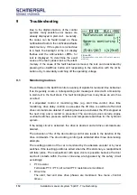
Due to the digital structure of the control
systems, many possible error causes are
already displayed in plain text. Generally,
the cause can be found based on these
notifications/faults in the notifications/faults
stack memory. If the system is locked due
to a fault, the backlight of the LC display
flashes and the abbreviation »SPE« for
lock is displayed. To determine the exact
cause of the fault, please look at the stack
memory. If the cause of the fault has been removed, the lock can be activated by
pressing the »Call/End« button and responding to the instruction with the »OK«
button or by momentarily switching off the operating voltage.
9.1
Monitoring routines
The software in the bp408 monitors a variety of signals for level and time behaviour.
If an irregularity occurs, a corresponding error message is stored with a timestamp
in plain text in the fault stack. The fault list displays how many times an error has
occurred.
If a stipulated control or monitoring time (e.g. start time control, drive time
monitoring, drive delay control) is exceeded, the lift drive is switched off and all
drive commands are deleted. If warning devices are activated, the lift is stopped at
the next stop and a restart is prevented. The warning devices include engine
overload switches, pressure switches and temperature switches for the hydraulic
system.
If the safety circuit is activated, the drive is aborted, and all drive commands are
deleted.
The activation of the of the door-locking control also leads to the deletion of the
drive commands. The door-locking control gets activated after three door-locking
attempts.
The levelling position of the car is monitored by the absolute encoder or by level
switches. If the levelling position is exited when the lift is stationary, a readjustment
will take place. The readjustment with open doors is possible because the door
and bolt contacts within the door zone area are bypassed by the safety circuit
accordingly.
PTC resistor
Terminals PTC / PTC, all current PTC resistors are monitored.
Drive time
The start, fast and slow drive phases are monitored. See menu
»Control
times«.
Figure 69:
Representation of an entry in the stack memory
with lock
.
Summary of Contents for bp408
Page 2: ......
Page 24: ...24 Installation manual of system bp408 Safety instructions...
Page 52: ...52 Installation manual of system bp408 The control system bp408...
Page 58: ...58 Installation manual of system bp408 Installation and assembly...
Page 80: ...80 Installation manual of system bp408 Electrical connection...
Page 118: ...Installation manual of system bp408 Appendix 118 Appendix A Menu navigation bp408...
Page 119: ...119 Installation manual of system bp408 Appendix B Update of the firmware via USB stick...

