7
- 124
Mini ECO-i System
Remote Control Functions
7
7. Communication Adaptor
(SHA-KA128AG(B))
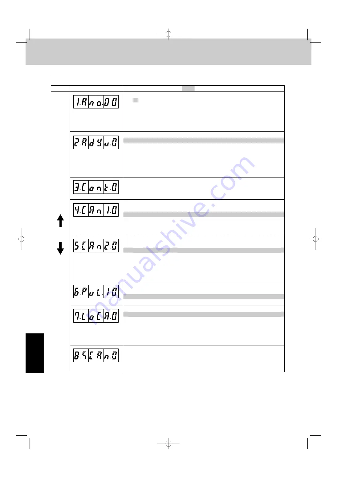
[1] Adaptor number setting
xx = 00 to 15: adaptor number
Sets the Communication Adaptor number.
Set 1 to 7 for the Intelligent Controller, making sure the same number is not used twice.
When actually communicating from a master system, the link system address LINK1 is 2n and
LINK2 is 2n + 1, where n is the Communication Adaptor number.
Thus, when the adaptor number is 2, the LINK1 address is 4 and the LINK2 address is 5.
[7] Local Adaptor connection settings
x = 0: LINK 1 on, LINK2 on
x = 1: LINK 1 off, LINK2 on
x = 2: LINK 1 on, LINK2 off
x = 3: LINK 1 off, LINK2 off
Set whether there is a Local Adaptor (for turning off and on) for each LINK system. If the setting is
“off”, startup will be faster as no Local Adaptor detection is run.
Table 1 Communication Adaptor setting items
Display
[2] Indoor/outdoor control wire connection settings
x = 0: LINK1 on, LINK2 on
x = 1: LINK1 on, LINK2 off
x = 2: LINK1 off, LINK2 on
x = 3: LINK1 off, LINK2 off
Set so any LINK (indoor/outdoor control wire) connected to the air conditioner is “on”, and any LINK
not connected is “off”.
* For solo installation (pulse meter dedicated), use x = 3: LINK1 and 2 both set to off.
(1.Ano.xx)
[3] Base unit settings
Always use 0 (the initial value).
(2.AdYu.x)
(3.Cont.x)
(4.CAn1.x)
(5.CAn2.x)
(6.PUL.xx)
(7.LoCA.x)
(8.SCAn.x)
[4] Settings for the number of Communication Adaptor units in one link, part 1
x = 0 to 7
x = 0: First Communication Adaptor in the LINK1 link
x = 1: Second Communication Adaptor in the LINK1 link
x = 7: Eighth Communication Adaptor in the LINK1 link
[5] Settings for the number of Communication Adaptor units in one link, part 2
x = 0 to 7
x = 0: First Communication Adaptor in the LINK2 link
x = 1: Second Communication Adaptor in the LINK2 link
x = 7: Eighth Communication Adaptor in the LINK2 link
Set the Communication Adaptor unit number for each LINK system when connecting multiple
Communication Adaptors to one indoor/outdoor control wire.
[6] Minimum pulse input detection time setting
x = 03: 30 msec
x = 10: 100 msec
If connecting a pulse meter with a pulse width between 30 and 100 msec, set to 30 msec.
[8] Initial communication setting
Always use 0 (the initial value).
Setting item ( grayed in areas indicate factory setting)
DOWN
UP
06-408 Mini_ECOi_SM7 11/10/06 7:24 PM Page 124
获取更多资料
微信搜索蓝领星球


