Sakura Tissue-Tek Polar DM Operating Manual Download Page 86


2-17


After Processing 

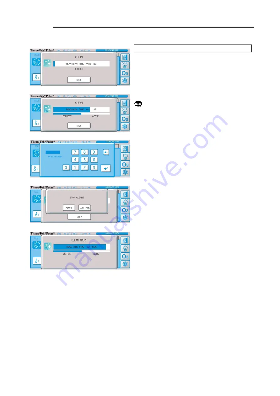
Cancelling Cleaning Operation   

1.  To cancel cleaning operation, you must enter the password.   
2.  Pressing the "Stop" button displays the cleaning operation 

cancellation password confirmation screen.   

Once the correct password is entered, the cleaning operation 
cancellation confirmation screen appears.   
If cleaning operation ends while this screen is displayed, the 
screen closes automatically.   
 

This password entry screen  is for aborting  the  cleaning 
operation, not for logging on the system.   


3.  Select "Abort," and defrost cycle operation will be cancelled if 

the cleaning operation consists of the defrost cycle only, after 
which the screen will close.   

If the ozone cycle is also set as part of the cleaning operation, 
the cleaning operation cancellation screen will appear and the 
ozone cycle will be cancelled. However, the ozone purge cycle 
cannot be cancelled.   
 

Summary of Contents for Tissue-Tek Polar DM

Page 1: ...Operating Manual Frozen Tissue Section Preparation Instrument Cryostat Microtome...

Page 2: ...nt cryostat microtome Tissue Tek Polar herein after simply referred to as the Polar instrument is an instrument to section frozen tissues Carefully read this Operating Manual and use the Polar instrum...

Page 3: ...e Right Panel DM only 1 11 How to Operate the Right Panel for Motorized Sectioning 1 11 Starting Motorized Sectioning 1 11 Pausing Motorized Sectioning 1 11 Stopping Motorized Sectioning 1 11 Adjustin...

Page 4: ...Setting Screen 1 39 Setting the Cleaning Operation Defrost Cycle Ozone cycle Start Time 1 40 Explanation of Scheduled Operation Setting Screen 1 41 Setting the Operation Ready Shutdown Times 1 42 Set...

Page 5: ...l Sectioning Final Shaving 2 11 Press the home position key to move the specimen head to the sectioning start position 2 11 Cutting the Specimen to Flat Surface Rough Shaving 2 11 Checking the Section...

Page 6: ...r 2 36 Plastic Object Holder 2 37 Using the Plastic Object Holder 2 37 Adapter for Cryo3 Object Holder 2 38 Using Adapter for Cryo3 Object Holder 2 38 Freeze the Block Using the PINO Hyfluid Method 2...

Page 7: ...Intake Grille 3 12 Replacement of the Brine Solution auxiliary cooling fluid 3 12 Chapter 4 Troubleshooting Troubleshooting 4 1 Before Suspecting a Trouble Instrument Conditions and Remedial Actions...

Page 8: ...roperty or negatively affect the processing result Point to note or other useful information Specifications and other details of the Polar instrument are subject to change without notice for the reaso...

Page 9: ...eavy objects on the power cord and store it in a narrow place Doing so may damage the power cord Do not place the instrument in a location exposed to direct sunlight snow or rain Ultraviolet rays and...

Page 10: ...ly causing fire accident failure etc Do not directly touch with hands etc those areas whose temperature drops to low levels Never directly touch with hands etc the chamber and other locations subject...

Page 11: ...Wear a mask gloves goggles and other protective gears while working or cleaning The Polar instrument has a blade and glass edges to demonstrate its characteristics Since these parts may cause injury...

Page 12: ...of power outage so the tissue sample may melt Also the disposable blade may frost and rust Do not leave the tissue sample and disposable blade in the chamber Set the chamber temperature and specimen h...

Page 13: ...ra distributor or representative If an error that cannot automatically be recovered occurs there might be ozone still inside the chamber Also even if an error can automatically be recovered to be extr...

Page 14: ...while the instrument is not in use If the instrument will not be used for an extended period of time be sure to close the window Otherwise the cooling part in the chamber may frost and cause the opera...

Page 15: ...Chapter 1 Basic Knowledge of Instrument...

Page 16: ...home position key 1 trim key etc let you section tissues in fewer steps The wide chamber also allows for smooth collection of sections Interior walls of the chamber are flat for easy cleaning 1 The h...

Page 17: ...ty The ambient operating temperature range of the Polar instrument is 10 to 35 C The ambient operating humidity range is 30 to 85 relative humidity non condensing Locate the instrument in a well venti...

Page 18: ...h This switch is used to stop the microtome operation Refer to p 1 13 for details 5 Right panel DM only Motorized sectioning can be started or stopped and the sectioning speed adjusted on this panel a...

Page 19: ...e levels The air volume can be checked with the center indicator lamp Refer to p 2 34 for details 16 Draft generator filter LEDs The two LEDs tell you when to replace the HEPA filter in the optional d...

Page 20: ...and the specimen head continues to advance while the key is held 5 TRIM key Turn the handwheel while holding this key to section the tissue to flat surface at a desired trim thickness according to th...

Page 21: ...is implement is used to prevent the section from curling Refer to p 2 13 for details 7 Anti Roll Plate This implement is used to prevent the section from curling Refer to p 2 14 for details 8 Blade ho...

Page 22: ...chamber To be specific the two move as follows When the handwheel is turned by one revolution from the condition in 1 to the condition in 4 the specimen head comes down 2 and the tissue is sectioned...

Page 23: ...er away from you The handwheel is locked when the specimen head is at the top position The handwheel is not locked if the specimen head is at any other position Note that turning the handwheel with th...

Page 24: ...to the movement of the specimen head during motorized sectioning Use the pause key on the right panel to unlock the foot switch Refer to p 1 10 for details Connecting the Foot Switch Connect the foot...

Page 25: ...or representative TYPE 1 Step on the foot switch once to start motorized sectioning Step on the foot switch again to start motorized sectioning TYPE 2 Hold the foot switch and the instrument continue...

Page 26: ...set each mode Refer to p 1 35 for information on how to set the sectioning end position Press the pause key and stop key together to start sectioning Do not turn the handwheel while sectioning is pau...

Page 27: ...he Cryomold The standard round type and square type have a knob for easy separation of the frozen tissue sample from the Cryomold Type Explanation Square type standard 26 x 31 mm Optional Used for sta...

Page 28: ...s the emergency stop switch EMERGENCY STOP appears on the screen and the motor stops immediately 2 Lock the handwheel to protect the tissue samples and then turn off the power switch of the instrument...

Page 29: ...toward you 2 Hold the knob on the blade guard and tilt it away from you to guard the tip of the disposable blade 3 To store the blade guard perform steps 1 and 2 in the reverse order The Anti Roll Pla...

Page 30: ...rred or otherwise the power was cut off during processing and the processing stopped recovery processing is performed once the system recovers The following operations are performed Defrost Manual ozo...

Page 31: ...e holder 20 mm from the specimen mounting base Sectioning auxiliaries Anti Roll Plate Anti Roll Rake Defrost cycle Hot gas heater Anti infection functions Ozone disinfection cycle Approx 75 minutes in...

Page 32: ...1 17 Standard Accessories Options 4 5 15...

Page 33: ...Anti Roll Rake F60 691 00 1 set 2 Anti Roll Plate F60 953 00 1 set 3 Blade holder D DM type F60 647 00 1 set 4 Heat extractor standard F60 622 00 1 unit 5 Parking plate standard O86 649 03 1 unit 6 Tr...

Page 34: ...TION Tab Manual motorized sectioning information and operations are displayed set and performed Refer to p 1 21 for details MOTORIZED Tab DM only Motorized sectioning information and operations are di...

Page 35: ...e cooling Once the cooling is started the snowflake icon changes as follows A short animation showing that chamber is being cooled is played switching from the standby mode and once the cooling temper...

Page 36: ...e temperature in the chamber The new temperature will also apply during motorized sectioning Refer to p 1 32 for details Specimen head temperature setting button Press this button to change the temper...

Page 37: ...and switch to the Temperature Setting 1 Temperature Setting 2 or FREE mode Section thickness setting button Press this button to change the section thickness to be used when sectioning Refer to p 1 30...

Page 38: ...and Press the Motorized Sectioning Mode Selection button to change the mode TRIM Mode Screen In the TRIM mode rough shaving is performed to the preset feed amount TRIM thickness While in the TRIM mode...

Page 39: ...rature Setting 1 2 mode Motorized sectioning mode selection button Press this button to select and switch to the TRIM FINE or PAUSE mode Section thickness setting button Press this button to change th...

Page 40: ...Tab become effective To change these temperatures change them in the FREE mode or Temperature Setting 1 2 mode Motorized sectioning mode selection button Press this button to select and switch to the...

Page 41: ...ng button You can set how much to offset the specimen head home position when moving to the home position following the pressing of the home position key Refer to p 1 34 for details Temperature settin...

Page 42: ...t TRIM Thickness and Draft Generator Refer to p 1 49 for the details of permissions Defrost button Start the defrost cycle manually as desired Refer to p 2 18 for details Shutdown button Start shutdow...

Page 43: ...GE button You can change the language Refer to p 1 46 for details Maintenance button Display maintenance information Refer to p 1 46 for details Cooling method button You can select Priority on Head T...

Page 44: ...be pressed when the first or last page of the list is displayed Refer to p 1 51 for details Output button This button can be pressed when a USB memory device is connected so that the error log list a...

Page 45: ...t saved and the screen closes automatically How to Change in the Motorized Sectioning Mode The section thickness can be changed only when the motorized sectioning mode is FINE or PAUSE If TRIM is sele...

Page 46: ...ectioning 1 Press the TRIM Thickness Setting button on the UTILITIES Tab Screen 2 The TRIM thickness change screen appears 3 Press the buttons among the Value Change buttons to change the value of sec...

Page 47: ...b Screen 2 The specimen head temperature setting screen appears The screen shows the measured value current temperature and setting value temperature to be set 3 Press the buttons among the Value Chan...

Page 48: ...to change and the value will be selected and highlighted 4 To change the chamber temperature press the value in the chamber temperature icon Press the buttons among the Value Change buttons to change...

Page 49: ...saves the setting after which the display returns to the TUNING Tab Screen If no operation has been performed for 5 minutes the setting is not saved and the screen closes automatically 5 Physically p...

Page 50: ...d to the setting position where you want to stop the specimen head As the handwheel rotates the specimen head in the chamber moves according to the value As long as the value is in the settable range...

Page 51: ...esired Suction Force 1 Press the Suction Force Setting button on the TUNING Tab Screen 2 The suction adjustment screen appears 3 Press the buttons among the Value Change buttons to change the value of...

Page 52: ...in the date selection area and the set date time is updated Set button Press this button to change the time Pressing this button displays the time change screen Save button Save the setting After the...

Page 53: ...Set button 4 Set the hours and minutes Press the value you want to change and the value will be selected and highlighted 5 To change the hours press the value of hours Press the buttons among the Valu...

Page 54: ...cannot press these buttons Refer to p 1 45 for details Exit button Return to the UTILITIES tab screen Automatic ozone cycle check box button If the check box is selected the ozone cycle will be perfo...

Page 55: ...r display hours is displayed in a range of 1 to 12 and minutes as a multiple of 15 minutes with am pm also shown 7 Pressing the Enter button saves the setting after which the display returns to the UT...

Page 56: ...to input output schedule data Note that the Everyone user cannot press these buttons Refer to p 1 45 for details Exit button Return to the UTILITIES tab screen Automatic ozone cycle check box button...

Page 57: ...ress the value of hours 6 Press the buttons among the Value Change buttons to change the value of hours In the case of 24 hour display Hours is displayed in a range of 0 to 23 and minutes as a multipl...

Page 58: ...switch to the previous month or button to switch to the next month The settable range is January 2000 through December 3000 5 Pressing the Save button closes the setting screen Deleting Days Off Setti...

Page 59: ...to switch to the next month The settable range is January 2000 through December 3000 5 Pressing the Save button closes the setting screen If a given day is set as both a day off and operating day it i...

Page 60: ...screen schedule displays the file transfer confirmation screen 2 Press Yes and the schedule information backed up to the CF card in the instrument will be loaded The currently set information will be...

Page 61: ...ance information is displayed Cumulative ozone lamp ON hours Cumulative compressor operating hours Cumulative Cryo operating hours 4 Press the close button to close the screen Setting the Cooling Meth...

Page 62: ...sound by pressing the Test button 4 Pressing the Save button saves the setting and closes the setting screen Changing the Sound 1 Press the Miscellaneous button on the UTILITIES Tab Screen 2 Press the...

Page 63: ...button displays the password setting screen 5 Use the numeric keypad to enter a password in the yellow password entry field Up to 6 digits can be entered The numbers from 1 to 999999 can be used but a...

Page 64: ...ature setting 1 32 1 33 Temperature setting mode change 1 21 Section thickness setting 1 30 MOTORIZED Tab Temperature setting mode change 1 24 Section thickness setting 1 30 End of section position 1...

Page 65: ...store button on the external input output screen password displays the file transfer confirmation screen 2 Press Yes and the password information backed up to the CF card in the instrument will be loa...

Page 66: ...ntly displayed press the Log List Switching button to switch to the event log 3 The event log list display area shows each event number and relevant information such as the Date Time on which the even...

Page 67: ...he software To update the software contact the nearest authorized Sakura distributor or representative Checking the Version 1 Press the Software button on the UTILITIES Tab Screen 2 Press the Exit but...

Page 68: ...1 53...

Page 69: ...Chapter 2 Operating Method...

Page 70: ...specimen head Adjust the specimen head Change the disposable blade Preparing for Sectioning Details p 2 4 Move the specimen head to the sectioning start position Cut the specimen to flat surface rough...

Page 71: ...r switch is found on the right side face of the Polar instrument Tilt the switch upward to turn on the power When the power is turned on the startup screen appears and shows the progress of startup pr...

Page 72: ...m the Sleep Mode If the screen is in the sleep mode press the Wake up button on the screen to switch to the password entry screen If the screen remains dark and nothing is displayed touch the screen o...

Page 73: ...ng the Specimen Head Temperature 1 Press the Specimen Head Temperature Setting button on the SECTION Tab Screen 2 The specimen head temperature setting screen appears 3 Press the buttons among the Val...

Page 74: ...een to start rapid cooling Continue cooling until the Cryo temperature drops to 50 C or below Cooling will continue for 15 minutes after the button is pressed To stop cooling press the Cryo button aga...

Page 75: ...en head 4 Refer to p 2 7 if the specimen head angle must be adjusted If compound etc is deposited on the installation surface or tapered part of the Object Holder or to the specimen head the Object Ho...

Page 76: ...ead up Angle adjustment locking lever This lever locks the vertical angle adjustment screw and lateral angle adjustment screw Raise the lever toward you to unlock the screws so that the angles can be...

Page 77: ...ently installed Refer to p 2 10 for details 4 Insert the new disposable blade between the blade holder and stage 2 5 Push out the old disposable blade if it still remains 3 6 Use the handle of a brush...

Page 78: ...te tilt away from you the blade holder left right lever shown in yellow to lock the blade holder If the blade holder stops moving to the left and right tilt all the way toward you the blade holder lef...

Page 79: ...3 7 Tilt away from you the disposable blade mounting lever indicated in red to lock the disposable blade 4 The Low Profile type refers to A35 S35 and C35 disposable blades among others How to Set the...

Page 80: ...imen head moves further The home position may not be appropriate depending on the height or orientation angle of the frozen block Turn the handwheel slowly to check the home position Press the home po...

Page 81: ...specimen by flattening the section using a brush etc It is recommended that you collect the fifth and subsequent sections because the first three or four sections tend to have unstable thickness due...

Page 82: ...ctioning and the tip of the Anti Roll Rake will be coupled and move forward on the stage by pulling the section 2 Remove the Anti Roll Rake by holding the section with a brush etc 3 Once a section is...

Page 83: ...the Anti Roll Plate and the stage return the Anti Roll Plate to its original position 4 Slowly move the glass slide closer to the section from above and the section will be attached to the glass slid...

Page 84: ...and pressing it again switches the vacuuming to the desired suction force Press the key one more time and suctioning will end If the suction force is currently set to 100 on the TUNING Tab Screen pres...

Page 85: ...cancelled Cleaning operation will be performed so long as all conditions are satisfied such as no operation for 30 minutes during the day 3 Cleaning operation starts and the cleaning operation progre...

Page 86: ...ion ends while this screen is displayed the screen closes automatically This password entry screen is for aborting the cleaning operation not for logging on the system 3 Select Abort and defrost cycle...

Page 87: ...n and the defrost operation cancellation confirmation screen will appear For details refer to the next item Cancelling Manual Defrost Cycle Do not leave the chamber with frozen blocks placed inside Th...

Page 88: ...peration cancellation confirmation screen will appear For details refer to the next item Cancelling Manual Ozone Cycle If alcohol was used in the chamber or waste tank dry the chamber tank completely...

Page 89: ...up time setting screen to stop cooling operation make the instrument sleep until the start date time after cleaning operation If Always on operation is selected for the schedule cleaning operation is...

Page 90: ...ar and remaining time If the check box for automatic ozone cycle is selected in the schedule the ozone cycle will be performed after defrost cycle Once the processing is complete the display changes t...

Page 91: ...ly after which the screen will close If ozone cycle is also set as part of the cleaning operation the shutdown cancellation screen will appear and ozone cycle will be cancelled However the ozone purge...

Page 92: ...t the automatic shutdown time 2 If Yes is selected on the automatic shutdown confirmation screen or the displayed wait time 5 minutes becomes 0 the instrument is automatically logged off and automatic...

Page 93: ...le this screen is displayed the screen closes automatically This password entry screen is for entering the password to cancel the processing so the instrument need not be logged on 3 Select Abort and...

Page 94: ...n the left shows an example of an error occurring during manual ozone disinfection A screen is displayed to inform the operator that ozone disinfection might have been insufficiently performed as a re...

Page 95: ...otorized sectioning Press the Motorized Sectioning Mode Change button on the MOTORIZED Tab Screen to change the mode TRIM mode In the TRIM mode you can automatically cut the specimen to flat surface r...

Page 96: ...every time each key is pressed Press and hold the key and the specimen head moves further Cutting the Specimen to Flat Surface Rough Shaving in the TRIM Mode Press the Motorized Sectioning Mode Chang...

Page 97: ...the MOTORIZED Tab Screen is currently not displayed or the handwheel is not yet unlocked an error sound is output and motorized sectioning cannot be started Besides manual sectioning you can use the...

Page 98: ...oll Plate falls sharply its front end may get contact with the disposable blade and broken This may lead to scatter of glass fragment and cause injury The broken Anti Roll Plate may also interfere wit...

Page 99: ...s Lever yellow Blade holder left right lever Unlock this lever to slide the blade holder to adjust its lateral position Refer to p 2 9 for details Lever blue Blade holder mounting lever Unlock this le...

Page 100: ...n wrench away from you the blade angle adjustment bolt found on the left side face of the blade holder The recommended angle relief angle stamped on the blade holder is 8 to 10 Once the position is fi...

Page 101: ...pter is used Do not put the blade holder mounting lever indicated in blue in the wrong hole 1 Set the blade holder over the blade holder locking projections in the chamber Make sure the top face of th...

Page 102: ...sert the metal plug into the normally used locking hole 3 put the screw into the threaded hole into which the metal plug was inserted and tighten the screw 4 3 Set the blade holder over the blade hold...

Page 103: ...erate the vacuum press the vacuum key on the left panel When a given suction force is currently set pressing this button once starts suctioning at 100 and pressing it again switches the vacuuming to t...

Page 104: ...the setting is not saved and the screen closes automatically Stopping the Draft Generator 1 Press the Draft Generator button on the UTILITIES tab screen 2 The draft generator setting screen appears 3...

Page 105: ...heat extractor at the tip of the arm installed on the Cryobar rail in the chamber 1 2 Put the heat extractor on the parking plate 2 3 Press the Cryo button among the buttons on the right side of the...

Page 106: ...ic Object Holder that does not conduct heat effectively Put tissue specimens in the Cryomold Put OCT compound by making sure it does not overflow Put the plastic Object Holder on top Make sure the sid...

Page 107: ...bject Holder is used Freeze the Block Using the PINO Hyfluid Method Frozen blocks can be prepared in approx 45 seconds using the PINO Hyfluid method Incompletely frozen blocks can also be cooled again...

Page 108: ...2 39...

Page 109: ...Chapter 3 Maintenance Inspection...

Page 110: ...e chamber to room temperature Wipe out disinfectant residue using a cloth damp with water and dry the chamber interior thoroughly If a disinfectant such as glutaraldehyde remains it may cause health h...

Page 111: ...ast 1 hour in 2 glutaraldehyde After the soak thoroughly rinse the tank under running water and dry it before setting in the instrument Wear a mask gloves goggles and other protective gears when handl...

Page 112: ...ct the connection port on the vacuum unit to the instrument side connection port in the chamber 1 Using the connected part 1 as the axis put the vacuum filter set on the vacuum filter setting base 2 2...

Page 113: ...instrument Refer to p 3 3 for the installation method Cleaning the Vacuum Hose If debris attach inside the vacuum hose its suction capacity will drop Clean the drain periodically Besides disinfectant...

Page 114: ...mality the LED lamp and suction level lamp start blinking turn to steady light to notify the situation The lamp modes and meanings are listed below If the particular situation you encountered is not l...

Page 115: ...bring it to a safety cabinet etc 4 Spray disinfectant alcohol on the draft generator placement area on the back of the instrument 5 Take out the draft generator from the bio hazard bag inside the safe...

Page 116: ...ethod from the chamber 2 Disassemble the moving part that slides to the left and right carrying the stage Tilt toward you the blade holder left right lever indicated in yellow to unlock the blade hold...

Page 117: ...ve washer spring and lever locking bracket for securing the stage in the chamber are set If the wave washer is not inserted the blade holder cannot be locked and sectioning won t be performed Be caref...

Page 118: ...t smoothly If not the right and left mounting plates are out of line Set the mounting plate so that it is parallel with the blade holder to avoid hitting it How to Install the Anti Roll Plate 1 If the...

Page 119: ...hten the glass locking screws Both top and bottom edges of the glass plate of the Anti Roll Plate can be used It is recommended to turn the glass plate upside down after one edge has been used for abo...

Page 120: ...tective gears when handling a disinfectant such as glutaraldehyde Thoroughly rinse the object holder with water after disinfected and dry it If a disinfectant such as glutaraldehyde remains it may cau...

Page 121: ...r or something Replacement of the Brine Solution auxiliary cooling fluid The brine solution must be replaced on a regular basis If the brine solution continues being used even after its replacement ti...

Page 122: ...3 13...

Page 123: ...Chapter 4 Troubleshooting...

Page 124: ...y 3 3 Isn t the desired suction force set low Raise the set value of desired suction force 1 36 The chamber cannot be cooled Isn t the setpoint temperature high Readjust the setpoint temperature 1 21...

Page 125: ...n of the handwheel Follow the instructions below to lessen the noise although it does not interfere with instrument operations 1 Loosen the vent cap to remove 2 Perform the automatic cleaning operatio...

Page 126: ...solve the problem 1 Remove the blade holder temporarily 2 Confirm the handwheel is locked 3 Raise the specimen head locking lever to place and lock the object holder on the specimen holder 4 Using th...

Page 127: ...This information is displayed immediately after the instrument is started and also after returning from the sleep mode If an unexpected problem occurred and the condition cannot be rectified easily tu...

Page 128: ...ile error occurred while the software was being updated Restart the instrument If the problem persists contact the Sakura authorized distributor 200 ABNORMAL CHAMBER SENSOR READING LOW TEMP Disconnect...

Page 129: ...horized distributor 360 WINDOW LOCK ERROR Unable to Lock the Window Open the window fully and then close the window If the problem persists contact the Sakura authorized distributor 361 WINDOW UNLOCK...

Page 130: ...e moved to the preset sectioning start position Log on log off Limit the instrument user by password entry The instrument is logged on when the password has been entered and logged off when the passwo...

Page 131: ...the instrument been used in a room where is in charge of pathology of infectious diseases Yes No 4 Has the instrument been used in a pathology laboratory for infectious diseases Yes No 5 Has the instr...

Page 132: ...ven during the warranty period 1 Malfunction and damage caused by a wrong handling 2 Malfunction and damage caused by a repair disassembly or modification performed by a party other than Sakura or Sak...

Reviews: